


Hardware Installation
2−56 CM 4000 Installation and Operating Manual
INSTALLING MACHINE CONTROL PANELS
MC 3000 Machine Control Panel and CP 3010 Expansion Panel
Installation of these panels is shown on page 2−37.
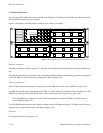
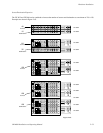
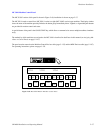
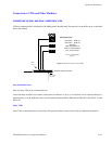
The MC 3000 machine control panel includes a series of push buttons for motion control (PLAY, STOP, etc.). A variable speed
knob, with a color−coded direction/speed indicator, is also included.
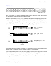
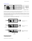
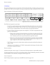
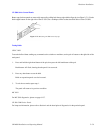
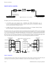
The machine to be operated can be selected using the adjacent CP 3010 expansion panel (Figure 2−68), which can display
the names of eight machines over a row of selection buttons. Additional pages of eight machines can be called up for display
in the window as required. The method by which machines are assigned to the CP 3010 is described in detail later in this man-
ual (see Assigning Machines to Control Panels on page 5−141). The CP 3010 can also be used as a limited−function machine
control panel, providing Start and Stop commands for VTRs.
The panels must be entered on the Machine Control Devices table (page 5−135) and the MPK Devices table (page 5−107).
For operating instructions, please see page 6−132.
Figure 2−67. MC 3000
machine control panel.
Variable speed
knob
Direction
indicator
SET
MARK
VARPLAY
STOPRDY SRCH
MARK
REC
OUT
REC
IN
REC
MODE
<< >>
>>
00:54:49:11 T1
VT01 STOP MAN
Status
STOP STOP STOP
VT01 VC01 VC02
Device
Figure 2−68. CP 3010
expansion panel.
∨
∧
>>>>>>>>
TAKE
———
SEL
TAKE
———
SEL
TAKE
———
SEL
TAKE
———
SEL
TAKE
———
SEL
TAKE
———
SEL
TAKE
———
SEL
TAKE
———
SEL