


2−1CM 4000 Installation and Operating Manual
Section 2 − Hardware Installation
Unpacking and Inspection
Each Jupiter Control System is tested, inspected, and found free of defects prior to shipment. Before unpacking the equipment,
inspect the shipping carton for evidence of freight damage. If the contents have been damaged, notify the carrier and Grass
Valley. Retain all shipping cartons and padding material for inspection by the carrier.
Do not return damaged merchandise to Grass Valley until an appropriate claim has been filed with the carrier and a material
return authorization number has been received from us.
Quick Start tip: If your Jupiter equipment was purchased from Grass Valley as a “turnkey”
system, you may wish to refer to the Jupiter Getting Started Guide, part no. 04-045707-003.
This booklet provides an abbreviated version of the information in this section.
110/230 VAC Selection
Most panels are auto sensing; otherwise, power line adjustments are normally made at the factory, based on the location of
the end−user. However, verifying these settings before applying power is a good practice.
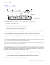
CP 300 Series Control Panels
These panels use an external power supply. See page 2−37.
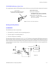
File Server
Check to see if the PC file server supplied with the system has a voltage selector switch for the power supply on the rear panel,
and if so, that the proper mains voltage is set.
Installation instructions for the file server begin on page 2−36.
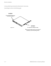
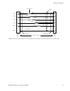
Rack Mounting
Grass Valley recommends that each control chassis be near most of the devices which it will control, thus reducing system
cabling. The CM 4000 Control Module should be located near the distribution switcher. See Figure 2−2 for the location of
the chassis fan and ventilation openings.