


Venus Monitor
O−2 CM 4000 Installation and Operating Manual
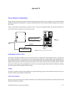
SOFTWARE CONFIGURATION
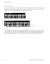
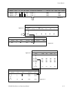
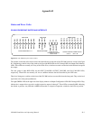
Figure O−2 is a block diagram of a Venus 64 x 64 switcher and its built−in 64 x 1 monitor switcher. In this example, the monitor
output (lower right corner) has been set with a jumper to the highest output number plus 1, or “64.” The crosspoint marked
“x” means that the monitor output has been switched to physical input 0 of the monitor switcher, which corresponds to physi-
cal output 0 of the Venus itself.
Various software tables must be used to establish the switcher as having 65 outputs; to assign a name and category/entry num-
ber to the monitor switcher output; and to assign a name and category/entry number to each monitor switcher input.
64 x 64 Venus switcher
23
04
1
5
0
1
2
3
4
6
7
5
0
1
2
3
4
6
7
“Out0”
“Out1”
“Mon”
A 0
A 1
“Out3”
A 3
“Out2”
A 2
Input
name
Physical
input
number
Category/
number
selection
“Out4” A 4
“Out5”
A 5
“Out6”
A 6
“Out7”
A 7
63
63
63 “Ou63”
A 6
64
Router inputs
Router
outputs
Monitor output
3
Misc 0
Internal 64 x 1 monitor
switcher
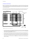
Figure O−2. Example of Venus monitoring system.
Output
name
Physical
output
number
Category/
number
selection
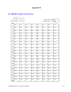
1. On the Switcher Description table, enter the Monitor Output Number (as shown in the documentation supplied with the
switcher) as the number of outputs for all levels. In this example, the number of outputs would be 65, even when some
of the levels have less than 64 outputs. See Figure O−3.
2. At the end of the Switcher Output table, create a name for the monitor output, and enter the corresponding physical out-
put number (Figure O−4). On an Output Set table, enter the output name and a Category/Entry number (Figure O−5).
3. At the end of the Switcher Input table, create names for the monitor inputs, and enter the corresponding physical input
numbers (Figure O−6). On an Input Set table, enter the input names and a Category/Entry number for each (Figure O−7).
Note the use of input names and mnemonics such as “OUT0;” these are to help the operator find the intended router
output for monitoring.