


Configurator
Switcher Description Table
5−41CM 4000 Installation and Operating Manual
In this example, the Green and Blue chassis would also have their Router Address switches set to “0000.”
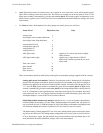
f. Conventional TVS/TAS square matrix switchers. For these switchers the hardware switches are usually set as
follows:
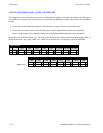
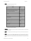
Name of level Physical level no.
Video 1
Left audio 2
Right audio 8
Time code 4
TVS/TAS data matrix forward/reverse level numbers: two levels must be described on the table—a forward level
and a reverse level; for TVS/TAS data matrix switchers the levels have different physical level numbers.
g. RKX switchers
††
. The physical level number can range from 0 to 99. Not supported by Jupiter XPress.
h. Multiple switchers.
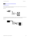
An example of a multiple switcher installation is shown on page 2−31.
As discussed in Step 3 above, more than one switcher can be operated by a single CM board; however, this will
require a unique hardware setting on each level to avoid conflicts. For example, you could enter a switcher “MAIN-
ROUT” with levels 1, 2, and 6; and switcher “NEWSROUT” with levels 3, 4, and 5.
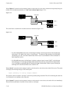
Alternatively, by dedicating a separate CM board to each switcher, the same physical level numbers can be used
on different switchers if desired. (See diagram on page 2−32.)
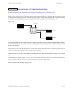
i. Logical level mapping (two logical levels on one physical level).
An example of logical level mapping is shown on page 2−29.
In these systems, the same physical level number can be used on more than one logical level (i.e., on more than
one row of the Switcher Levels table). For example, you could enter a switcher “MainRout” with Left Audio on
level 2, and with Right Audio also on level 2. This technique can sometimes help reduce overall switcher size, but
it requires special entries to this table and to the Switcher Outputs table as follows:
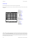
— the Switcher Levels table must always show the total number of outputs for the entire physical level. For the
example system shown on page 2−29, the matrix entry would be “60 x 60” for the Left logical level, even
though the level is being used as a 60 x 30. The same applies to the Right logical level; the table entry would be
“60 x 60.”
— the Switcher Outputs table (page 5−55) must indicate the differing physical output numbers used on each
level. For example, output “VT01” might use physical output “20” for video and left audio and physical out-
put “21” for right audio.
††
When an RKX and a Grass Valley Crosspoint Bus switcher are entered on this table, an offset of 100 can be used to avoid
having the same level numbers for both switchers. See also footnote marked with “
†
” on next page.