


Hardware Installation
2−17CM 4000 Installation and Operating Manual
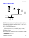
JUPITER CONTROL OF ENCORE
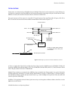
The CM 4000 can send switching commands to a Grass Valley Encore control system (which can in turn send the commands
to a router).
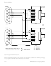
The serial ports on the back of the Encore System Controller Board (SCB) use RJ45 connectors; the port selected for the CM
connection must be configured for RS−422 operation with an internal jumper. For more information about the SCB ports,
refer to the Encore installation and user manuals.
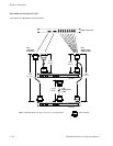
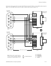
Non−Redundant Installation
See Figure 2−18.
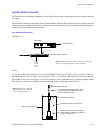
Figure 2−18. Connection to non−redundant Encore Control
System. See following figures for cable variations.
to routing switcher
Encore SCB
RS−422 port
House time
code
(optional).
See pg.
2−64
CM 4000 System Controller
Serial Port
LAN
Cabling
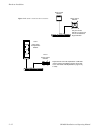
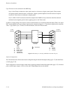
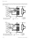
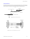
A Cat5 factory cable kit is available in two versions: If the SCB is the old style (071 0884 xx series), order kit 174 8216 xx.
If the SCB is the new style (071 1000 xx series), order kit 174 8217 xx. The factory cable must be used with a customer−sup-
plied adapter, wired as shown in Figure 2−19. Note that the factory cable is eight inches long. A customer−supplied standard
Cat5 cable (and coupler) can be added if needed. Further instructions are provided with the cable kit.
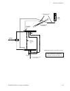
Figure 2−19. Factory−supplied
Encore/Jupiter serial cable and
customer−supplied items
RJ45 female to 9−pin D male adapter at-
taches directly to CM serial port. Internal
wiring is per Figure 2−21.
8−inch cable supplied with Encore Y Cable
Kit. (Type depends on SCB model; refer to
text for ordering information.)
To SCB RS−422 port
Customer−supplied items
Standard Cat5 cable (max. 250 feet)
Standard Cat5 coupler