


Replacement CM 4000
K−2 CM 4000 Installation and Operating Manual
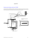
REPLACING A FAILED UNIT
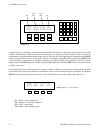
A fault condition should be indicated by a “00,” “01,” or “FF” indication on the front panel LED display, or, in the case of
a failed power supply, no lamps illuminated. Control should have switched to the other CM by this point. Check that it has
by looking for the green Activate lamp. Then proceed as follows:
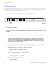
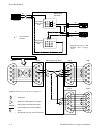
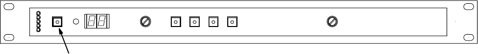
1. If necessary, switch control manually to the good unit by pressing the Activate button.
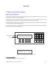
Figure K−2
.
Activate
button
DOWN
RESET
ACTIVATE
+3V
+5V
−5V
+12V
−12V
UP
NEXT SELECT
2. De−power the faulty CM 4000.
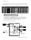
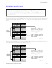
3. Before installing the replacement unit, change its physical Ethernet address (MAC address) to match that of the failed
CM 4000:
Caution: Changing the physical address of the CM 4000 can have undesirable results if not done properly. It
is very important to maintain strict control of the addresses of all units in and out of the system to avoid net-
work conflicts.
The physical Ethernet address is stored in a serial EEPROM chip. The data in this chip is validated with two
checksums. If either checksum is invalid, the Ethernet chip will fail to initialize and will not function. Be-
cause of this, it is very important that during the EEPROM write procedure, the CM 4000 is not reset or power
interrupted until the write cycle is completed.
a. On the replacement CM, connect a terminal to the front console port and power up the unit. It is stressed that this
procedure is done with the replacement CM 4000 out of the system where there can be no address conflict.
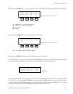
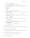
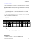
b. Stop the boot process at the ‘Press any key to stop auto−boot.’ prompt.
Press any key to stop auto−boot...
1
c. At the VxWorks boot prompt, enter ‘N’ and then press ‘enter’.
[VxWorks Boot]: N [ENTER]
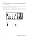
d. Wait for the EEPROM memory to get read:
Reading EEPROM ..................................