


Configurator
CP Output Set
5−87CM 4000 Installation and Operating Manual
When finished, skip to Step 17.
13. DD (“Diamond”) − E−MEM
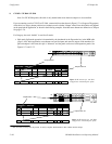
For DD applications, both E−MEM and Serial tables will probably be required. The dual entries are necessary because
of the two hardware connections, as previously described (page 2−60).
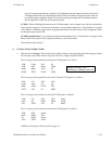
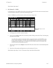
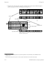
For the E−MEM table, you will need entries similar to that shown in Figure 5−68.
1
Output Set — DIA−OUT
dflt 1 DD01
2
3
dflt 2 DD02
dflt 3 DD03
4 dflt 4 DD04
5
6
dflt 5 DD05
dflt 6 DD06
128 dflt 128 DD128
Figure 5−68. Output Set table
(example).
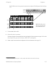
Category Entry Mnemnonic
Output
Level Set Button
Logical
a. For Category, the word “dflt” is used for all entries.
b. Specify the desired Entry number. This can be done by double−clicking on the desired “Entry” field and typing
the number. Press ENTER.
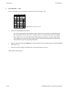
Note: These Entry numbers must match the numbers assigned to the buttons on the DD M/E Bus, using
the DD “Install > Ident Input > Ident Xbar” menu. Each DD button that is fed from the router should
be assigned an Entry number from 1 to 128. Refer to the DD installation manual for information about
the DD serial ports and operating instructions.
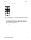
c. Enter the name of the first router Output wired to the DD. The source of these names is the Switcher Output table
(page 5−55).
d. Enter the next Entry number and Output name, up to the maximum of 128 rows.
When finished, skip to Steps 17 and 18. Then return to Step 2 and build the DD serial table.