


GV 8964OMD OSD Module
CM 4000 Installation and Operating ManualT−4
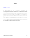
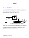
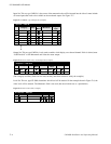
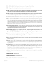
Input Set. This set, type UMD3A, is the source of the mnemonics that will be inserted into the video. It must include
all router inputs that need to be available to the monitored output. See Figure T−7.
Figure T−7. UMD3A−type CP Input Set (example).
Input Set — OSD−IN
Category Entry Mnemonic
Input
2
3
Test 1 BARS BARS
VTR 1 VT01 VT014
5
Test 2 TONE TONE
Test 3 CODE TC
VTR 2 VT02 VT02
CAM 1 CAMERA 1 CAM16
Auto
Mnem
Logical
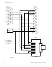
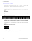
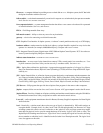
Output Set. This set, type UMD3A, is only used to enable a clock display on a selected channel. If this is desired, enter
“@@Time@@” as the Mnemonic and select the router output.
Figure T−8. Clock−enable entry on CP Output Set (example).
1
Output Set — OSD−OUT
TEST 1 @@Time@@ STU1
2
Category Entry Mnemnonic Level Set Button
Auto
Mnem
Output
Logical
(The Category and Entry fields are not used, but they must have entries to satisfy the compiler.)
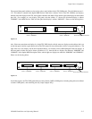
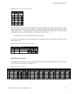
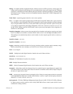
Level Set. This set, type CP 3800, determines which level will be statused. In the example shown in Figure T−9, the
video level will be statused. The Mnemonic field is not used (but must include text as a placeholder).
Figure T−9. CP Level Set table (example).
1
CP Level Set — OSD−LEV
Mnemonic Level Break Switch
2
aaaa VIDEO