


CP 3000 Basic Operation
J−2 CM 4000 Installation and Operating Manual
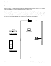
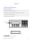
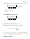
Figure J−3.
VTR
1
CG
2
NET
3
SAT
EJVCR
4
CAM
5
REM
6
FILM
7
PTCH
8
STU
9
FS
AUX TEST
0
MISC SS
A
B
C
D
TAKECHOPLOCKPROT
F4F3F2F1
MORECLRMENULEV
VTR1 VT1L VT1R VT1T
BLK BARS TONE SLNC
Vid
Aud
Ch1
TC
Aud
Ch2
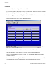
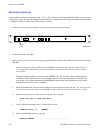
Looking at Figure J−3, the display window shows the home menu. This includes, in the top row, the status of the video, audio
channel 1, audio channel 2, and timecode levels. In the bottom row, it displays the override selections. These overrides are
selected when you push the function button directly below it. This gives you a one button push in conjunction with the TAKE
button to call up whatever source is in the display column. For example, pressing F1 and then pressing the TAKE button
would select black as the source to the destination the panel is controlling. Another way of selecting a source is to use the
keypad and then the TAKE button. For example, pressing VTR and then 1 and then the TAKE button would select all levels
of VTR1 as the source.
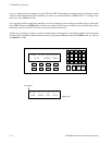
Since this panel can access any destination (for example, an input to a VTR), you must select the destination that the panel
is controlling. This panel can only control one destination at a time. To select or change the panel’s destination, you press the
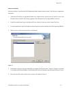
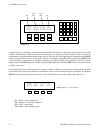
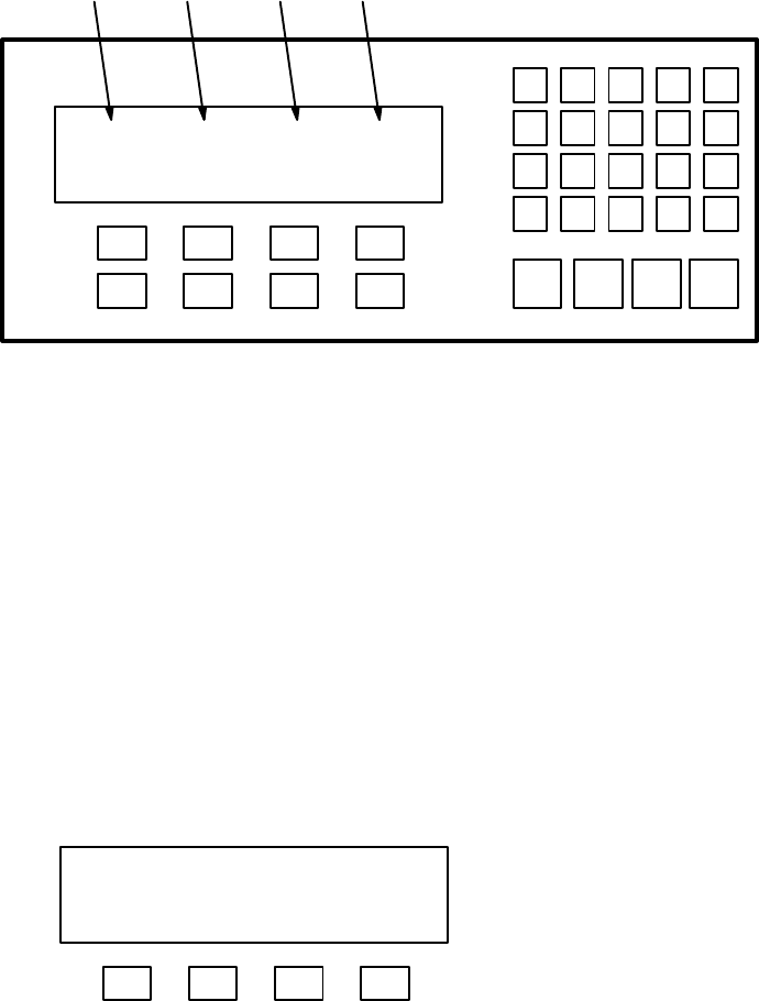
MENU button. Once this button has been pressed, it will change the bottom row of the display (See Figure J−4).
F4F3F2F1
Figure J−4. Page 1 of menu display.
VTR1 VT1L VT1R VT1T
STAT SEQ AUD OUT
F1 = Status − display output status
F2 = Sequence − select input sequences
F3 = Audio − audio modes
F4 = Output − display/change output