


Hardware Installation
2−60 CM 4000 Installation and Operating Manual
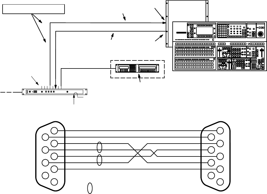
CONNECTION TO THOMSON/PHILIPS DD SERIES (“DIAMOND”)
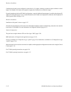
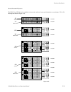
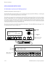
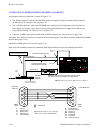
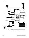
An example of hardware connections is shown in Figure 2−72.
• The “Diamond protocol” cable to one of the DD serial ports is required for display of routing switcher status on
the DD console. For cable pin−outs, see page 2−63.
• The “ASCII bus protocol” cable to the DD XBAR port is required if switch commands will be sent from the
DD to Jupiter; for example, when a Venus router is used to provide additional AUX outputs for the DD, or used
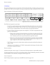
to provide Pre−Routing. For cable pin−outs, see Figure 2−73.
• If desired, an MPK control panel could be used for DD Pre−Routing. For cable pin−outs, see page 2−63.
“Diamond” and “ASCII” protocols are set on the Serial Protocol table (page 5−30); and the switcher is identified on the MPK
Devices table (page 5−123).
Installation of MPK panels was discussed on page 2−38.
Refer to the DD installation manual for information about the Diamond serial ports and operating instructions.
“Diamond protocol”
Serial port 1,
2, or 3
ASCII bus protocol
XBAR port
for Mnemonic Status to DD
for AUX extension switch
commands from Diamond
Figure 2−72. Connections to DD switcher (example).
MPK panel may be used as alternate method of send-
ing switch commands to Jupiter (CP−3000 shown).
MPK protocol
CM 4000
System
Controller
Serial
Ports
House sync required for
vertical interval switching.
LAN
See discussion on page 2−60 for in-
formation concerning these cables.
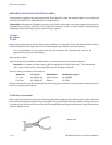
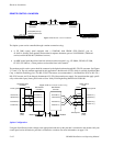
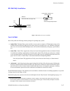
Figure 2−73. Cable for connecting CM
4000 to Grass Valley DD XBAR Port.
1
6
R−
2
7
3
T−
8
4
9
5
TA
RB
to CM 4000
serial port
to DD XBAR Port
G Ground
R− Receive minus
R+ Receive plus
T+ Transmit plus
T− Transmit minus
DB9P
(male)
DB9P
(male)
= twisted pair
1
6
2
7
3
8
4
9
5
T+
TB
R+
RA
G G
RC
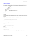
G Frame Ground
TC Transmit common
RA Receive A
RB Receive B
TB Transmit B
TA Transmit A
RC Receive common
TC