


Hardware Installation
2−63CM 4000 Installation and Operating Manual
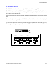
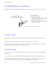
Installing CM 4000 VGA Status Display
Please refer to Appendix A for installation instructions.
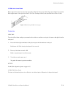
Serial Data Cables
The RS−422 cables used to connect CM 4000 controllers, VTRs, and control panels may be known by various names depend-
ing on the devices to which they are connected. Thus a particular serial bus might be called the “Sony bus,” the “MPK bus,”
etc. In spite of the different terminology, each of these buses consist of a 4−conductor (plus ground) cable.
Maximum length per bus is 1220 meters (4003 ft).
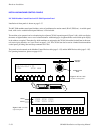
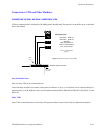
The rear panel serial data cable connectors on the CM 4000 and MPK control panels are 9−pin D, female. The CP and MC
connectors are arranged for loop−through wiring. No termination is required. While these connectors are ESbus compatible,
it should be noted that the Grass Valley serial data cables use only 5 of the 9 pins described in the ESbus specification (Appen-
dix F).
The following ready−made cables, with installed 9−pin D male connectors, are available from Grass Valley (VDE* cables
include ferrite cores):
1 meter (3.3 ft) 8 meters (26.2 ft)
2 meters (6.6 ft) 16 meters (52.5 ft)
4 meters (13.1 ft) 32 meters (105 ft)
For ordering information, see page 1−22.
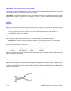
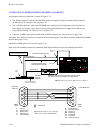
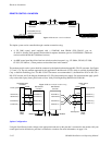
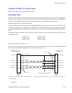
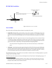
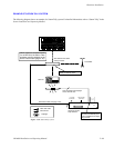
For those who wish to prepare their own cables, the pin−outs are shown in Figure 2−77. The cable itself should be Belden
8723 or equivalent. Details concerning ferrite cores are given in Figure 2−78.
1
2
3
7
8
1
2
8
P1
DB9P
(male)
Shield (drain)
Green
Black
White
P2
DB9P
(male)
Figure 2−77. Serial data cable wiring. Reference: “Assembly, BCS−3000 Serial Data Cable,” Grass Valley drawing no.
01−041600−TAB.
3
7
Red
Frame ground
CM 4000 controller board
(bus controller)
Control panel or VTR
(tributary)
Receive A (−)
Transmit A (−)
Receive B (+)
Transmit B (+)
Transmit B (+)
Transmit A (−)
Receive B (+)
Receive A (−)
Frame ground
Individually shielded, twisted pairs
Ferrite core
Ferrite core
Green
Black
White
Red
*see Glossary.