


Configurator
Path Finding
5−178 CM 4000 Installation and Operating Manual
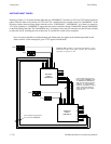
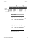
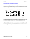
PATH FINDING FOR THREE OR MORE SWITCHERS
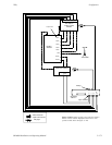
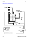
Connecting three switchers for path finding purposes possible, with five as the recommended maximum. This is illustrated
in Figure 5−154. Notice that no tie lines directly connect switcher “A” and switcher “C.”
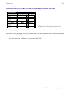
In the corresponding Path Finding Data table, there would be descriptions of the tie lines from “A” to “B,” from “B” to “A,”
from “B” to “C,” and from “C” to “B.”
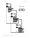
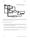
Note: There may be situations where wiring would allow manual selection of alternate routes. In Figure 5−154,
this would be the case if video lines also existed between switcher “A” and switcher “C. ” However, the Jupiter
path finding software cannot take advantage of such alternate routes; in other words, it does not “switch around
busy areas.” Only one possible route between each pair of switchers can be described on the Path Finding Data
table when the system is configured.
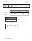
There would also be Group entries in the Switcher Input tables of all three switchers:
— For the switcher “A” table, the names of sources available through path finding would all be referenced to the
tie lines from switcher “B” to “A.” This would include the sources wired directly to switcher “C.”
— For the switcher “B” table, the names of sources available through path finding would be referenced to the tie
lines from switcher “A” to “B,” or, from “C” to “B,” as appropriate.
— For the switcher “C” table, the names of sources available through path finding would all be referenced to the
tie lines from switcher “B” to “C.” This would include the sources wired directly to switcher “A.”
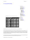
In general, path finding entries are needed only for switchers that are immediately adjacent. The system will use this informa-
tion to find paths involving one or more intermediate switchers.