


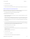

Configurator
Switcher Input Table
5−53CM 4000 Installation and Operating Manual
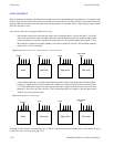
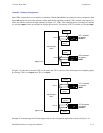
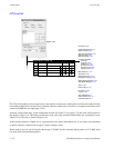
Controller / Tributary Reassignment
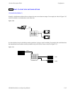
Some VTRs can themselves act as controllers or tributaries. With the DM 400B the associated ports can be configured as both
inputs and outputs; this allows their pinouts to adjust automatically depending on which VTR is selected as the output (con-
troller) and which is selected as the input (tributary). In Figure 5−41, VTR 1 is the controlling device; accordingly it is selected
as a switcher output in order to configure the switcher port correctly. The tributary VTR 2 is selected as a switcher input.
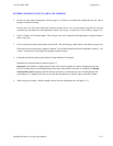
Port 01
Controller
pinout
Tributary
pinout
Tributary
pinout
Controller
pinout
Port 02
DM 400B Data
Matrix
VTR 2 selected
as switcher
INPUT
VTR 1 selected
as switcher
OUTPUT
Figure 5−41.
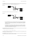
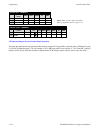
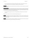
In Figure 5−42, the roles are reversed. VTR 2 is the master and VTR 1 is the slave. The switcher ports are configured properly
by selecting VTR 2 as an output and VTR 1 as an input.
Port 01
Tributary
pinout
Controller
pinout
Port 02
DM 400B Data
Matrix
Controller
pinout
Tributary
pinout
VTR 2 selected
as switcher
OUTPUT
VTR 1 selected
as switcher
INPUT
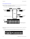
Figure 5−42.
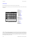
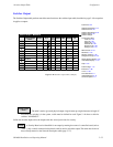
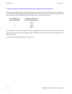
Examples of Switcher Input and Switcher Output tables for this reassignment application are shown in Figure 5−43.