


Configurator
CP Input Set
5−63CM 4000 Installation and Operating Manual
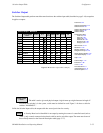
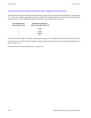
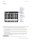
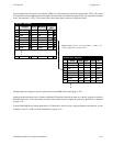
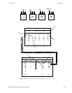
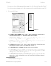
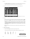
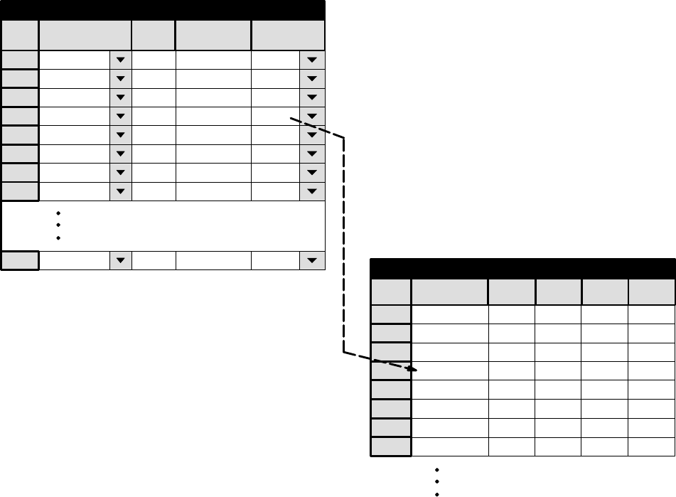
In the example shown in Figure 5−48, selecting VTR/1 on a control panel will call for the input named “VT01.” The system
will look on the Switcher Inputs table for this input name and switch to the indicated inputs; in this case, input 001 for all four
levels. The mnemonic “VT01” will be used in the control panel status windows to report the switch.
Figure 5−48. Selection of Category/Entry “VTR/1” will
switch to input 001 on all four levels.
1
Input Set — KXYZ−INP
Category
Entry Mnemonic
Input
2
3
Test 1 BARS BARS
VTR 1 VT01 VT014
5
Test 2 TONE TONE
Test 3 TC TC
VTR 2 VT02 VT02
VTR 3 VT03 VT03
VTR 4 VT04 VT04
VTR 5 VT05 VT05
MISC 8 ESS ESS
6
7
8
n
1
Name
BARS
RIGHT
VIDEO
2 TONE
3
TC
4 VT01
5 VT02
6
7
8
VT03
VT04
LEFT
000
001
002
003
004
VT05 005
000P
001
002
003
004
005
000P
001
002
003
004
005
000
000P
001
002
003
004
005
Switcher Input − MainRout
064II
000I 000I 000I
TC
Logical Input
Logical
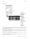
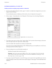
The Input Sets are assigned to specific control panels on the MPK devices table (page 5−107).
Although each control panel can be assigned a different CP Input Set if desired, the same set is usually assigned to all panels.
Different Output Sets, on the other hand, are often used to control access to outputs on a panel−by−panel basis as described
on page 5−78.
In Venus DM 400B data switching applications, a CP Input Set is used to assign a category/number and mnemonic to each
“tributary” (such as a VTR). For more information, see page 5−52.