


Hardware Installation
2−64 CM 4000 Installation and Operating Manual
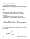
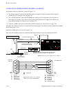
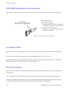
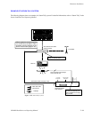
VDE EMI/RFI Modifications to Serial Data Cables
User−supplied serial data cables for VDE installations require a ferrite core over each end of the cable, adjacent to the connec-
tor.
Figure 2−78. Serial data cable VDE modifications.
Type 43 material
0.250 inch (6.35 mm) inside diameter
0.95 inch (24.13 mm) length (or longer)
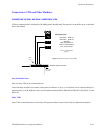
Type 43 material sources
Fair−Rite, part no. 2643480002
Fair−Rite Products Corp., P.O. Box J, Commercial
Row, Wallkill, NY 12589, USA; Tel. (914) 895−2055.
Chomerics, part no. 83−10−A636−1000
Chomerics Inc., 77 Dragon Ct., Woburn, MA 01888
USA; Tel. (617) 935−4850.
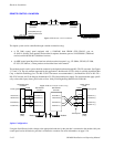
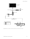
Sync Reference Cables
A video reference (sync) signal should be connected to each Jupiter controller board (including the CM 4000 System Control-
ler).
This signal may be color black or composite sync with an amplitude between 1 V P−P and 4 V P−P.
The CM 4000 System Controller must have a sync reference in order for a Grass Valley Crosspoint Bus router to switch during
the house vertical interval. Crosspoint Bus routers are listed on page 1−11.
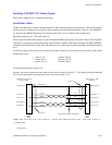
Time Code Connections
Time code must be connected to the CM 4000 for deterministic switching (AccuSwitch application). For more information,
see Appendix G.
A time code connection to the CM 4000 also provides an accurate date and time stamp for JNS Logger messages (page 12−1).
If desired, the CM 4000 clock and the file server clock can be synchronized by referencing them to the same time source, such
as a time code input (preferred) or a Network Time Protocol server. See page G−11 in Appendix G.