


Control Panel Operation
VGA Display
6−138 CM 4000 Installation and Operating Manual
VGA Status Display Operation
The VGA Status Display provides a supervisory, system−wide display of switcher, machine, or system status. The display
video is provided by the VGA output of a CM 4000. The display format is initially based on a set of factory default pages,
but can be customized as needed. (For more information about installation and configuration, see Appendix A.)
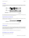
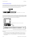
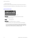
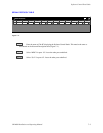
Basic controls for this display are located on the front panel of the CM 4000 (Figure 6−169).
Figure 6−169. VGA controls on CM 4000
DOWN
UP
NEXT SELECT
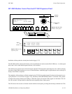
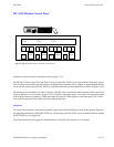
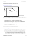
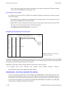
For easier operation, the CM 4000 can be connected to one CP 3020 control panel, which in this application is configured
as device type “VC 3020” (see Figure 6−170). To use the VGA to best advantage, it should also be connected to a CP 3000
Switcher Control Panel and an MC 3000 Machine Control Panel. The RGB display monitor and the controls just described
should be located as close together as possible, preferably in the same equipment rack.
Figure 6−170. VGA Status Display control panel arrangement.
CP 3020 control panel, showing suggested labels for VC 3020 application
CP 3000 MC 3000
NEXT
CURSOR
MODE
CHNG
MODE
0 912345678
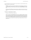
Philips WXYZ TELEVISION ROUTER/VTR STATUS PAGE: 00
May 10, 1999 SWITCHER STATUS 12:34:56
−−−−−−−−−−−−−−−−−−−−−−−−−−−−−−−−−−−−−−−−−−−−−−−−−−−−−−−−−−−−−−−−−−−−−−−−−−−−−−−−
OUTPUT VIDEO LEFT RIGHT TC
−−−−−−−−−−−−−−−−−−−−−−−−−−−−−−−−−−−−−−−−−−−−−−−−−−−−−−−−−−−−−−−−−−−−−−−−−−−−−−−−
PrdA VT01 VT01 VT01 VT01
PrdB VC01 VC01 VC01
PrdC Cam1 Cam1 Cam1
PrdC Cam1 Cam1 Cam1
PrdC Cam1 Cam1 Cam1
PrdC Cam1 Cam1 Cam1
PrdC Cam1 Cam1 Cam1
PrdC Cam1 Cam1 Cam1
PrdC Cam1 Cam1 Cam1
PrdC Cam1 Cam1 Cam1
PrdC Cam1 Cam1 Cam1
PrdC Cam1 Cam1 Cam1
PrdC Cam1 Cam1 Cam1
PrdC Cam1 Cam1 Cam1
PrdC Cam1 Cam1 Cam1
PrdC Cam1 Cam1 Cam1
PrdC Cam1 Cam1 Cam1
PrdC Cam1 Cam1 Cam1
PrdC Cam1 Cam1 Cam1
PrdC Cam1 Cam1 Cam1
PrdC Cam1 Cam1 Cam1
PrdC Cam1 Cam1 Cam1
PrdC Cam1 Cam1 Cam1
PrdC Cam1 Cam1 Cam1
PrdC Cam1 Cam1 Cam1
PrdC Cam1 Cam1 Cam1
PrdC Cam1 Cam1 Cam1
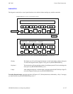
The VGA display starts up on Page #0 as defined in the VGA Page Description File. Display pages 0−9 are selected with the
number buttons.
Note: Page decades are accessed using 9+UP ARROW or 0+DOWN ARROW. For example, for pages 10−19,
press “9,” then UP ARROW; the “0” button will light indicating page 10, and the number buttons will select pages
10−19. To return to pages 0−9, press “0,” then DOWN ARROW; the “9” button will light and the number buttons
will select pages 0−9.