


Control Panel Operation
VGA Display
6−139CM 4000 Installation and Operating Manual
The following discussion is based on the factory default set of display pages.
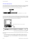
SWITCHER OUTPUT STATUS PAGE
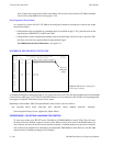
Thomson WXYZ TELEVISION FACILITY CONTROL SYSTEM PAGE: 01
May 10, 1999 MAIN Switcher Output Status 12:34:56
−−−−−−−−−−−−−−−−−−−−−−−−−−−−−−−−−−−−−−−−−−−−−−−−−−−−−−−−−−−−−−−−−−−−−−−−−−−−−−−−
OUTPUT VIDEO LEFT RIGHT TC
−−−−−−−−−−−−−−−−−−−−−−−−−−−−−−−−−−−−−−−−−−−−−−−−−−−−−−−−−−−−−−−−−−−−−−−−−−−−−−−−
PrdA VT01 VT01 VT01 VT01
PrdB VC01 VC01 VC01
PrdC Cam1 Cam1 Cam1
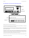
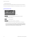
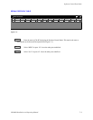
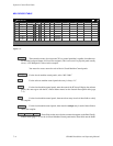
Figure 6−171. Switcher out-
put status page (example)
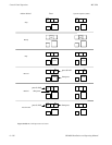
Levels
Outputs
Inputs
A switcher output status page (Figure 6−171) can provide a list of switcher outputs and the name of the input switched to each.
Separate columns for each level can be used to report split switches; these can be highlighted with a distinct color.
An alternating (flashing) display indicates that the output is locked or protected:
• The first flashing character shows “L” if the output is locked; “P” if the output is protected.
• If a single flashing character is shown next, it indicates a special control device (i.e., not an MPK panel) has set
the the lock or protect. “A” is for an ASCII protocol device (e.g., an automation computer); “S” is for an ES−
switch protocol device (ditto).
• The following characters show the name of the locking/protecting device. The name is taken from (or short-
ened from) that shown on the MPK Devices table.
NEXT is used to cycle through additional logical switchers (if any). UP and DOWN (or the arrow buttons on the CP 3020)
will step through additional pages of outputs; hold the key down to auto−repeat.
Cursor Mode − Selecting an Output for Control
To enter cursor mode, press SELECT on the CM 4000 (or CURSOR MODE on the CP 3020). This will cause
the name of the first output to appear in reverse video. The UP and DOWN buttons (or arrow buttons) will move
the cursor from one output to another. An output pointed to by the cursor is automatically selected as the output
to be controlled by the CP 3000 Switcher Control Panel associated with the CM 4000 providing the VGA display.
Note 1: If an output cannot be switched, it may be that the output or input requested is not included in the CP
Output Set assigned to the CP 3000. See page 5−114. This may also be the case if asterisks appear in place of
the normal status indication.