


Configurator
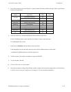
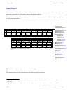
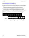
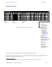
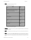
Switcher Description Table
5−37CM 4000 Installation and Operating Manual
This method of enforcing vertical interval switching applies only to Grass Valley switchers operating on the Crosspoint
Bus port of the CM. For “remote serial control” applications, including Triton, VI should be unchecked on all levels.
5.
RV
Reverse switching. This item applies only to certain data switchers. For video, audio, and time code switchers,
leave unchecked.
This box is checked for older model RS−232/422/423 data switchers equipped with DM 400/400A
§
Data Matrix boards.
Configuration of DM 400/400A Data Matrix boards is described in Appendix L.
Newer model data switchers equipped with DM 400B
§
Data Matrix boards use only one level, and the “RV” box is left
unchecked (even though “reverse” switching is still taking place).
6.
MC
Select machine control assignment follow Yes or No for this level. Normally checked for video level and un-
checked for all others. One (only) level can be checked.
As explained in detail elsewhere in this manual, the usual procedure is for the machine assignment system to follow the
distribution switcher; that is, if a certain VTR is selected for a certain destination, then the associated machine control
panel will automatically assume control of that VTR. (See Assigning Machines to Control Panels on page 5−141 for more
information.) This menu item determines which level will be used as the reference in making the machine assignment.
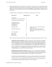
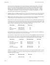
7.
Board
Select the name of the CM 4000 controlling this level.
The source of these names is the Network Description table (page 5−27).
Each logical level can be controlled by a separate CM 4000.
Redundant CM boards, if any, are ignored on this table. Recall that redundant CM boards have the same logical name.
Using a single CM, one or more Grass Valley Crosspoint Bus routers can be connected to the Crosspoint Bus port.
Triton routers, or certain non−Crosspoint Bus routers, can be connected to a CM 4000 serial port.
§
Type and model of switcher card is shown on front edge of printed circuit board.