


Venus DM 400/400A
L−4 CM 4000 Installation and Operating Manual
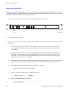
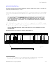
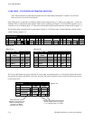
As an alternative scheme, it is possible to use the same entry in the “Switcher” column (for example, “MAINROUT”) for
all levels, including the data levels (Figure L−4). In this case, the Switcher Input and Switcher Output tables will have columns
for all switcher levels.
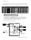
Figure L−4.
Name chosen for data router must sort alphabetically before names used
for other switchers (e.g., “M” comes in the alphabet before “O.”
1
Switcher Description
MAINROUT M1 64 64 1 Binary None
2 MAINROUT M1 64 64 2 Binary Left
3 MAINROUT M1 64 64 8 Binary Right
4 MAINROUT M1 32 32 4 Binary None
VIDEO
LEFT
RIGHT
TC
Switcher VI RV Board #In #Out PLvL Follow Level Driver 3 LI 3 LO Option AudioLevel
DM 400
MC
Off Time
5 MAINROUT M1 193 32 16 Binary EFOR
6 MAINROUT M1 193 32 16 FOR (MAINROUT) Binary EREV
7 OLDROUT M1 10 10 3 TVS ProtVIDEO
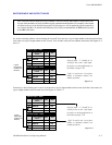
Note: A limitation in the present software requires that the entries in the “Switcher” column for the data router
levels must be the same as or come alphabetically before all other names used in the Switcher column. In Figure
L−4 this rule is satisfied because the entry “MAINROUT” in rows 5 and 6 is the same as the entry in rows 1 through
4, and because the letter “M” in “MAINROUT” comes alphabetically before the letter “O” in “OLDROUT.” This
does not mean that the entries must be in alphabetical order within the table itself.
For a discussion of the ”DM 400 Off Time” entry, see page 5−47.
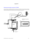
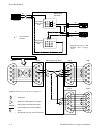
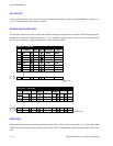
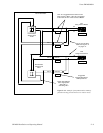
Figure L−5. Example
of DM 400/400A Data
switching system.
Rx
Tx
Rx
Tx
“EDITOR”
“VCR1D”
“VCR2D”
Forward data
switcher level
“FOR”
03
02
02 04
03
Reverse data
switcher level
“REV”
Port 02
Port 04
DM 400/400A
Data Matrix
04
This crosspoint
selected
=
Tx
Rx
Port 03
“D−1”
“C−1”
“D−2”
Suggested
Category/Number for
control panel use.
=
“C−1”