


Hardware Installation
2−7CM 4000 Installation and Operating Manual
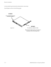
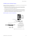
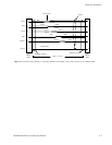
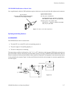
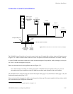
VDE EMI/RFI Modifications to Matrix Cables
User−supplied matrix cables for VDE installations require a ferrite core over each end of the cable, adjacent to the connector.
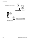
Figure 2−7. Matrix cable VDE modifications.
Type 43 material
0.375 inch (9.53 mm) or larger inside diameter
0.95 inch (24.13 mm) length (or longer)
Type 43 material sources
Fair−Rite, part no. 2643625102
Fair−Rite Products Corp., P.O. Box J, Commercial
Row, Wallkill, NY 12589, USA; Tel. (914) 895−2055.
Chomerics, part no. 83−10−A637−1000
Chomerics Inc., 77 Dragon Ct., Woburn, MA 01888
USA; Tel. (617) 935−4850.
System protection features
ALARM MODES
The CM 4000 master alarm is asserted when:
• The main CPU (or a main CPU task) is not operating properly, or
• The power supply is not operating properly, or
• The unit is in the process of rebooting.
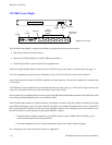
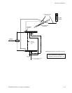
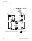
The master alarm condition is indicated by a “00,” “01,” or “FF” indication on the front panel LED display, and at the rear
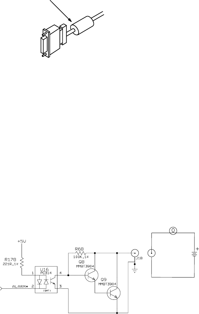
panel Alarm BNC connector. Electrically, the Alarm BNC operates according to SMPTE standard 269M−1999. When an
alarm is asserted, the circuit associated with the Alarm connector will present a low impedance to an external current source
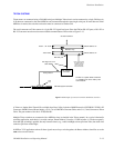
circuit provided by the customer. Figure 2−8 shows the CM alarm circuit (left) and an example of a customer−supplied indica-
tor circuit (right).
EXTERNAL CIRCUIT
(EXAMPLE)
NOT TO EXCEED
24 VDC @ 20 mA
REAR−PANEL BNC
Figure 2−8.