


Hardware Installation
2−13CM 4000 Installation and Operating Manual
TRITON SYSTEMS
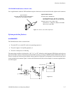
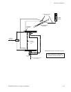
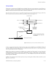
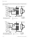
Triton routers are connected using a CM 4000 serial port. Multiple Triton chassis can be connected to a single CM, but only
if all them are connected on the same MIDI bus and connected through the same single serial port. If more than one Triton
MIDI bus is needed, the switchers on that bus must be connected to another CM.
The serial connector on Triton routers is a 9−pin RS−232 signal level port. Since the CM has RS−422 ports, a RS−422 to
RS−232 converter must be used to ensure reliable communications. Please refer to Figure 2−13.
Figure 2−13. Example of connection to Triton distribution switchers.
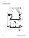
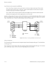
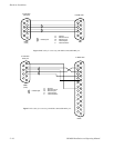
See Figure 2−14 for
cable details
Triton protocol
†
A Triton−to−Jupiter Serial Control Kit
is available from Grass Valley. See
text for details.
RS−422/232
converter
†
RS−232 port
MIDI bus loop
Triton Video
Triton L + R Audio
20 units maximum
Router address “0”
Router address “2”
House sync required
for vertical interval
switching (analog
units). See Triton
manual for details.
CM 4000 System Controller
Serial
Ports
LAN
A Triton−to−Jupiter Serial Control Kit, available from Grass Valley, includes a B&B Electronics 422COR RS−232/RS−422
Converter, a B&B Universal Power Supply, a 25 ft. (7.6 m) VM/CM to Converter Cable, and a 5 ft. (7.6 m) Converter to Triton
Cable. The part number of this kit is 44-050456-001.
Multiple Triton switchers are connected with a MIDI bus loop (as detailed in the Triton manual). In a typical video/audio
switching application, each chassis is set with a unique “Router Address” from 0 to 15 (DIP switches 1−4 on the rear panel).
Note that split switching is possible, but only between chassis; e.g., Audio Left/Right can be split from Video, but Audio Left
cannot be split from Audio Right.
In RGB or YUV applications where all three signals must always switch together, the Router Address should be set to the
same value on each chassis.