


Configurator
MPK Devices
5−119CM 4000 Installation and Operating Manual
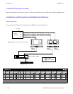
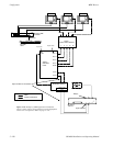
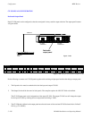
SYSTEMS WITH SATURN MASTER CONTROL AND PRODUCTION SWITCHER
If UMD status from a production switcher upstream of Saturn is needed, the “Jupiter control” method must be used. “Jupiter
control” of UMDs is based on the software used for tally light control. See page 5−120 for an example system of this type.
Note : “Jupiter control” cannot be used to status inputs connected to the Saturn Internal Matrix Option.
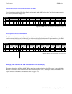
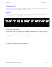
Each UMD must named on the MPK Devices table (page 5−121).
The address of SlimLine displays is set using front−panel switches. For more information, see page 5−117.
Special Output Set tables of type “UMD3a” must be created to name all router outputs that can be selected for the Preset,
Program, and Air busses.
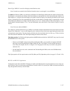
The MI 3040 used to collect status information from the production switcher must be named on the MPK Devices table.
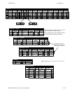
An “MCS_TLY” entry is required to allow the Jupiter system to gather status information from the Saturn. This entry will
be similar to row 5 of the MPK Devices table on page 5−121.
Note : The device called “MCS_TLY” exists only in software tables. Saturn systems require a “Board” entry that
points to the Video Processing Unit; the “Port” number is always “1.” For MCS 2000 systems, the “Board” entry
points to the controller connected to the MCS−2000; the “Port” number is always “7.”
If there is more than one master control switcher in the system, there must be an entry for each—for example, with the Device
Names “MCS_TLY1,” “MCS_TLY2,” etc.
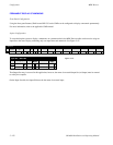
The Output sets, Tally Relay, and Tally Dependency tables are created as shown. Note that these entries allow for operation
of a tally light connected to Relay 3 on the MI 3040 (if desired).
For information about activating UMD built−in tally lights, see “Tally Light Operation” on page 5−117.