


Hardware Installation
2−51CM 4000 Installation and Operating Manual
CP 3864 Control Panel
VTR1 VTR2 VTR3 VTR4
VTR5 VTR6 VTR7 VTR8
CAM1 CAM2 CAM3 CAM4
CAM5 CAM6 CAM7 CAM8
BLACK
BARS TONE CG−1
SILENCE
CG−2 CG−3 CG−4
EBS1 EBS2 TEST1 TEST2 FDL1 FDL2 FDL3 FDL4
MON1 MON2 MON3 MON4
MON8MON6MON6MON5
STU1
STU2 STU3 STU4
EDIT1 EDIT2 EDIT3 EDIT4
PST PGM AIR KEY1
KEY2
BACK
UP
BY
PASS
XMIT
VTR1 VTR2 VTR3 VTR4
VTR5 VTR6 VTR7 VTR8
Level Menu Clear
Chop
Lock/
Prot
Pre−
set
Take
CURRENT
PRESET
DESTINATION
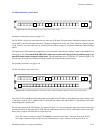
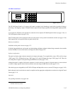
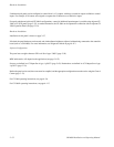
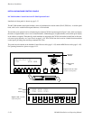
Figure 2−61. CP 3864.
VTR−041
VTR−041
MONITOR5
The CP 3864 is a multiple−level* breakaway* panel which is capable of locking,* protecting,* and chopping* outputs. The
panel features eight−character display capability and relegendable, lighted push buttons.
The panel can also be configured as a type “CP 3864L,” in which the upper right−hand group of six buttons are used for level
selection and the panel operates in “sticky levels”* mode. In this case, the “Level” button shown in Figure 2−61 is used to
access the first level in the panel’s Level Set (typically video), the “Menu” button is used for the second level (e.g., left audio),
etc. The Take button is used as a Protect key.
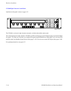
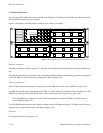
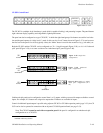
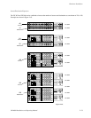
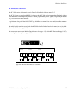
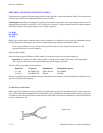
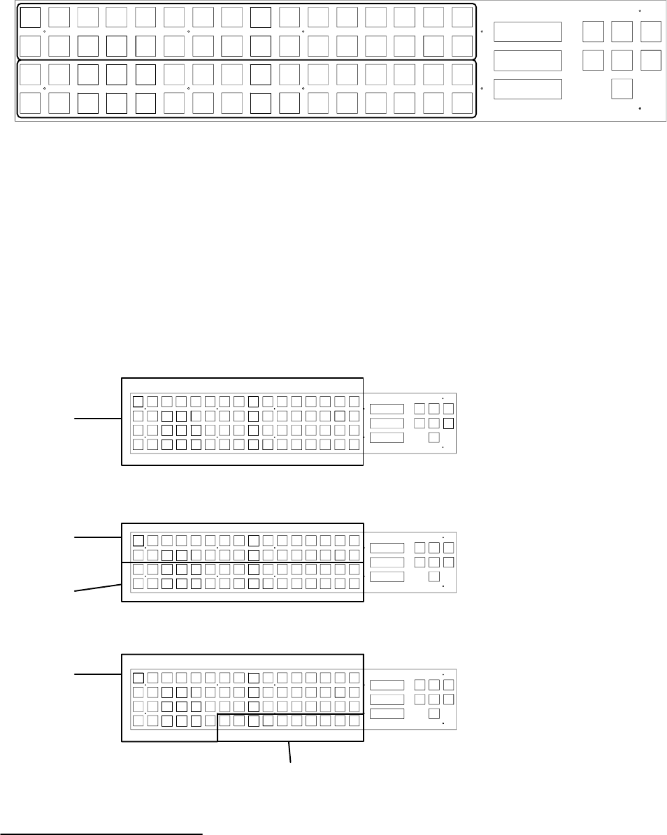
The CP 3864 Control Panel can be configured as a 64 x 1 single bus (Figure 2−62), as a 32 x 32 “balanced split” panel (Figure
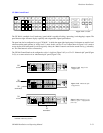
2−63), or as some variation of an “unbalanced split” panel (Figure 2−64).
Figure 2−62. Single−bus
configuration.
64
sources
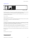
Figure 2−63. “Balanced split”
configuration.
32
sources
32
destinations
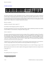
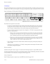
Figure 2−64. Example of “un-
balanced split” configuration
(54 x 10) .
54
sources
10
destinations
* Defined in Glossary Section