


Configurator
CP Output Set
5−90 CM 4000 Installation and Operating Manual
16. CP 3832 / CP 3864 / CP 3810
Note: For CP 3832/64 panels, this table is only needed when more than one output is to be controlled.
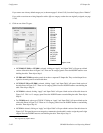
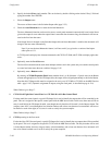
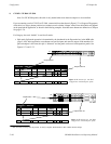
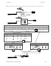
If you are entering a set for CP 3832 or CP 3864, a menu similar to that shown in Figure 5−71 will appear. The purpose
of the table is to assign a button position (row number) to each switcher “Output” name. Exact table entries will depend
on the panel and the application, as shown in the following examples. Note that source buttons are defined on a CP Input
Set (page 5−74).
For Category, the word “default” is used for all entries.
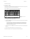
S Split mode. Split mode operation is determined by the checkmark in the Expansion box in the MPK table
(page 5−109). In this application, some buttons are used for inputs and some for outputs. If the number of in-
puts and outputs is the same, the split is “balanced” and the panel can be used with expansion panels. See
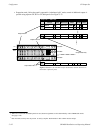
Figures 5−71 and 5−72.
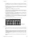
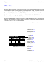
1
Output Set — 3832−OUT
default 1 MONITOR1 MON1
2 default 2 MONITOR2 MON2
16 default 16 VTR−4 VTR4
Output button 1
CP−3832
Output button 16
IN
OUT
†
†
†
Figure 5−71. Entries for CP 3832
configured as “balanced split” panel.
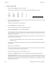
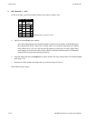
Category Entry Mnemnonic
Output
Lev Set Button
Logical
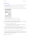
Output button 1
CP−3864
Output button 32
IN
OUT
Figure 5−72. Entries for CP 3864
configured as “balanced split” panel.
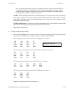
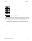
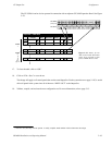
1
Output Set — 3832−OUT
default 1 MONITOR1 MON1
2 default 2 MONITOR2 MON2
32 default 32 VTR−12 VT12
†
†
†
Category Entry Mnemnonic
Output
Lev Set Button
Logical
†
Data not used, but entry must be present to satisfy compiler. Each number in this column must be unique.