


Venus DM 400/400A
L−5CM 4000 Installation and Operating Manual
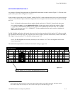
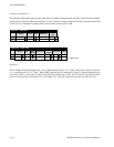
SWITCHER INPUT AND OUTPUT TABLES
Note: Since the software depends on logical numbers, which are actually row numbers on these tables, edit-
ing one of the the tables can easily break the logical connection between them. For example, if new inputs
are added to the top of the Switcher Input table, all following rows will be pushed down and assume new
row (logical) numbers. To minimize this difficulty, Grass Valley recommends that all NEW entries be made
at the end of the tables.
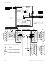
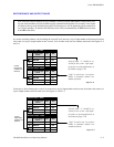
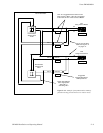
In a reverse switching scheme, a device feeding the “forward” level must use a logical input number on the forward level that
is the same as its logical output number on the “reverse” level. In other words, the row numbers must match. See Figures L−5
and L−6.
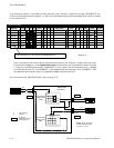
Figure L−6.
1 SAFE
FOR
2 EDITOR
3 VCR1D
4 VCR2D
REV
192
002
004
192
002
004
Switcher Input − DATA
003 003
Logical
input/output
numbers are
identical
Logical input “1” should be re-
served for use as the “safe input”
for point−to−point applications, as
described on page 5−45.
“Safe” is used in row 1 as a place
holder to maintain relative row
number positions.
Name
Logical Input
1 SAFE
FOR
2 EDITOR
3 VCR1D
4 VCR2D
REV
002
004
Switcher Output − DATA
003
Name
Logical Output
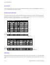
Conversely, a device feeding the “reverse” level must use a logical input number on the reverse level that is the same as its
logical output number on the forward level. See Figures L−5 and L−7.
Figure L−7.
1 SAFE
FOR
2 EDITOR
3 VCR1D
4 VCR2D
REV
192
002
004
192
002
004
Switcher Input − DATA
003 003
Logical
input/output
numbers are
identical
Logical input “1” should be re-
served for use as the “safe input”
for point−to−point applications, as
described on page 5−45.
“Safe” is used in row 1 as a place
holder to maintain relative row
number positions.
Name
Logical Input
1 SAFE
FOR
2 EDITOR
3 VCR1D
4 VCR2D
REV
002
004
Switcher Output − DATA
003
Name
Logical Output