


CP 3000 Basic Operation
J−3CM 4000 Installation and Operating Manual
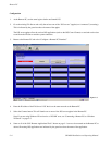
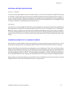
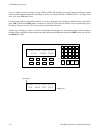
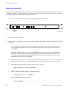
By depressing the MORE button, you will call up page 2 of the menu. The function buttons change to represent the following:
F4F3F2F1
Figure J−5. Page 2 of menu display.
VTR1 VT1L VT1R VT1T
DIAG DEF PWD LOG
F1 = Diagnostics − control panel diagnostics
F2 = Define − re−define input overrides
F3 = Passwords
F4 = Logout
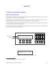
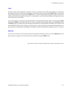
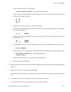
By depressing the MORE button, you will call up page 3 of the menu:
F4F3F2F1
Figure J−6. Page 2 of menu display.
VTR1 VT1L VT1R VT1T
ID
F1 = ID − display control panel device address
By pressing the MORE button again, you will toggle back to page 1 of the menu.
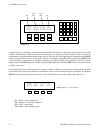
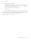
For the present time, we want to go to page 1 and press the F4 button; this will allow us to change what destination the panel
is controlling. The bottom display row will now show PANEL OUTPUT = VTR2. (See Figure J−7.)
Figure J−7.
VTR1 VT1L VT1R VT1T
PANEL OUTPUT = VTR2
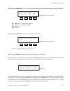
Now any selection made from the keypad area of the controller will change the panel’s destination. For example, with “PAN-
EL OUTPUT =” showing, pressing the VTR button, the 2 button, and the TAKE button, you have now selected the panel
to control what feeds VTR2. Be aware, however, any time the bottom row of the display shows “PANEL OUT =”, anything
you press on the keypad and then press TAKE will change the destination of the panel.