


O−1CM 4000 Installation and Operating Manual
Appendix O
Venus Monitor Configuration
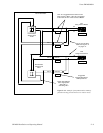
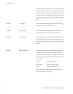
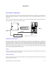
When used with a Jupiter control system, the Venus output monitoring hardware allows verification of switcher performance
without interrupting normal operations. A separate switching system is used to switch the Monitor Output to any output of
the switcher.
Using a control panel, the operator picks an output as usual—in this case, the Monitor Output. The operator then selects an
input, but this input is actually one of the switcher outputs.
QC
STATION
CROSSPOINT
BUS
CONTROL SYSTEM
MPK BUS
Audio and video from
Monitor outputs
SWITCHER CONTROL
PANEL
Figure O−1. Venus monitoring overview.
HARDWARE INSTALLATION
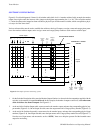
The number of the Monitor Output, which is used during software configuration, is determined by factory−set jumpers on
the switcher motherboard. At the output card slots, the output number used is the output number for the output monitor. In
larger, multi rack systems, all output cards are set to the same output number. By convention, this number should be the next
output number range above the last real output in the system. On a 352 by 64 switcher system, the output numbers would be
from 0 to 63. The output monitor would then be 64. In all cases, the monitor output number should be confirmed by checking
the documentation package supplied with the switcher.
Cabling
For details concerning external cable connections for output monitoring, please see the Installation Section of the Venus
Installation Manual, part number 04-044592-004.
VM/DC 400 Combiners
The Venus Installation Manual also describes installation of the VM 400 Analog Video Monitor Combiner and the DC 400
Digital Video Monitor Combiner.