


Control Panel Operation
CP 3000
6−19CM 4000 Installation and Operating Manual
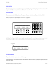
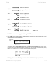
Left signal on Left channel
Right signal on Right channel
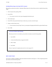
“NORM” =
“LEFT” = Left signal on Left channel
Right signal on Right channel
Right signal on Left channel
“RGHT” =
Left + Right signals on Left channel
Left + Right signals on Right channel
“MIX” =
Right signal on Left channel
Left signal on Right channel
“REV” =
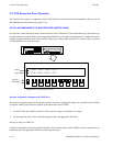
Figure 6−21.
Left signal on Right channel
The “REV” mode is on the second page (accessible using the MORE key).
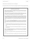
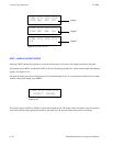
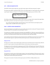
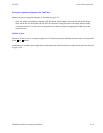
6. Press TAKE. This will complete the special switching operation and exit the audio mode. A flashing letter “A” will
appear on the normal status/override display:
Figure 6−22.
VTR1 VT1L VT1R VT1T
ABLK BARS VTR1 VTR2
Audio caution
symbol
This flashing symbol is a caution that the top row of the display does not show true status. In this example, “VT1R”
is indicated as the source for the right audio channel, but in fact VT1L is the source. This can be determined by pressing
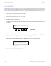
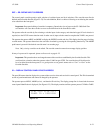
MENU, AUD, and the soft−key for the desired level to bring up the following display:
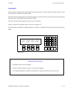
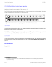
Figure 6−23.
LEFT RGHT MODE: LEFT
NORM LEFT RIGHT MIX
This display shows true status. The left input channel is switched to both the left and right output channels.