


Configurator
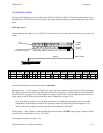
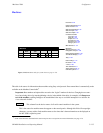
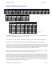
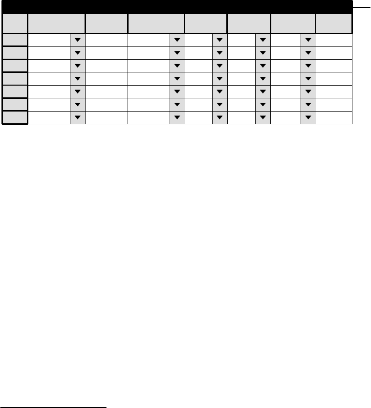
Machine Control Table
5−139CM 4000 Installation and Operating Manual
Machine Control
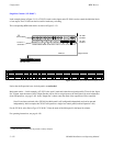
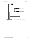
Figure 5−120.
1
Machine Control
Device Name Device Type
Delegation
In/Out
Associated
2
TAPEMC
MC−3000E Out PRDA
3
Mnemonic
TAPEMC
VT01
Sony Mch In VT01
VC01 Sony Mch In VC01
VC02
Sony Mch In VC02
4
Group Name
VT01
VC01
VC02
TAPEMC MC−3000E Out PRDBTAPEMC5
TAPEMC MC−3000E Out PRDCTAPEMC6
TMC3010 MC−3010 Out PRDXTMC30107
Preroll
2
2
2
Password 5−22
Network Description 5−27
Serial Protocol 5−30
Switcher Description 5−35
Switcher Input 5−48
Switcher Output 5−55
Control Panel Sets
Level set 5−58
Input set 5−62
Output set 5−78
Override set 5−96
Sequence set 5−99
Category set 5−101
MPK Devices 5−107
Machines 5−135
Machine Control
Delegation Groups 5−149
Status Display Header 5−150
VGA Status Display 5−151
Tally 5−152
Path Finding 5−174
Exclusion 5−188
Y Line 5−189
Time Standard G−11
Video Reference G−14
CM VGA Options H−1
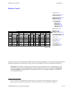
This table is used to associate machines, machine controls, and router inputs/outputs in order to provide automatic machine
assignment functionality (“control follows video”).
§
It is also used when a PC is used as a Software Control Panel.
†
Important: Row numbers on Jupiter tables are used as the “logical” numbers for devices. Changing the row num-
ber of an existing device (by inserting/deleting a device in the middle of the table, for example) will disrupt con-
trol of the machine, requiring linkages to be reestablished. One way to avoid this interruption is to add new de-
vices at the end of tables.
§
Some of the functions described in this section may be extra−cost options. For more information, see page 1−27.
†
Applies only when the Software Control Panel is used for machine control. For more information, see Section 7.