


Hardware Installation
2−77CM 4000 Installation and Operating Manual
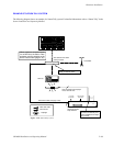
MI/MC 3040 Hardware Overview
Reset
Gen.
Osc.
3.6864MHz
RESET
68HC705
PORT A
PORT B
PORT B
RS−422
Driver/Receiver
TO MPK
40
Optical
couplers
40
Opto−
electronic
relays
Relay
Interface
LCA
MI−3040R
Optical status
interface
LCA
MI−3040S
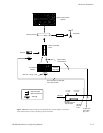
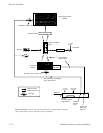
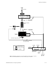
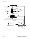
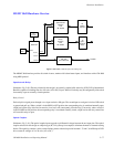
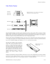
Figure 2−89. MI/MC 3040 interface block diagram.
Data/Address Bus
Control
The MI/MC 3040 interface provides 40 switch closures, monitors 40 isolated status inputs, and interfaces with a CM 4000
using MPK protocol.
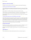
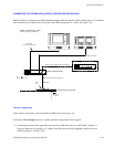
Optoelectronic Relays
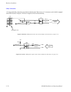
(Reference: Fig. 2−90.) The relay selected for this design is an optically−coupled solid−state relay (PVD1352 by International
Rectifier) capable of switching from 0 to 100 volts (AC or DC) at up to 300 mA. Each relay may be configured by slide switch
for normally−open or normally−closed operation.
Relay Control
Each relay drive signal passes through a two−input exclusive−OR gate. The second input to each gate is tied to a DIP switch
to ground and pull−up. When a switch is in the OPEN or OFF position, the corresponding relay is considered normally open;
a high level on the relay drive line (inverted to a low level) will consequently close the relay. Conversely, when a switch is
in the CLOSED or ON position, the corresponding relay is considered normally closed; a high level on the relay control line
will cause this relay to open.
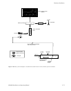
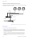
Optical Couplers
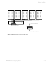
(Reference: Fig. 2−91.) The optical coupler inputs respond to a differential voltage between the two input pins. The optical
couplers selected for this design are a bipolar type (PC314 by Sharp, for example) to eliminate the need for external steering
diodes. The signal leg contains a series current−limiting resistor selected to provide between 1.75 and 13.6 milliamps of LED
drive current at voltages of 5 to 28 volts (AC or DC).