


CM 4000 Installation and Operating Manual Q−1
Appendix Q
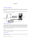
PS 300 110/220 VAC Power Adaptor Kit Installation Instructions
This kit (assembly part no. 44−046442−001) provides all hardware needed to modify one CP 300 Series control panel for
direct connection to a 110/220 VAC power line. The CP 300 Series includes the CP 300, CP 310, CP 320, CP 328, and CP
330.
The kit includes an add−on chassis (which mounts on the rear of the panel) and a detachable, 3−prong AC power cord. The
chassis measures approximately 12 in. wide x 5 in. deep x 1−3/4 in. high and includes a TE/PE grounding strap and fuse
holder.
MOUNTING PROCEDURE
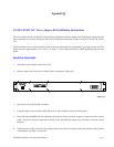
1. Disconnect control panel, remove from rack.
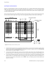
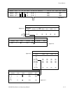
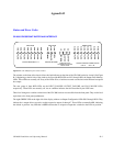
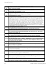
2. Remove eight screws from rear of control panel as indicated in Figure Q−1.
Figure Q−1.
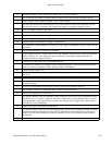
3. Open top cover of PS 300 add−on chassis.
4. Using the eight screws provided, attach top cover of add−on chassis to rear of control panel.
5. Insert DC plug and MPK 9−pin D connectors from add−on chassis into their respective connectors on the control
panel. Secure the 9−pin D connectors with the screws provided (the ribbon wires will have a half−twist when
finished).
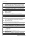
6. Slide lower half of add−on chassis into position. Secure with twelve #4 counter−sunk screws (three on the top, three
on the bottom, and three on each side).