


Software Control Panel Suite
7−4 CM 4000 Installation and Operating Manual
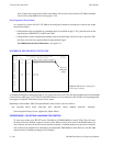
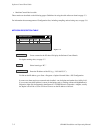
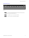
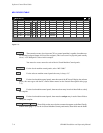
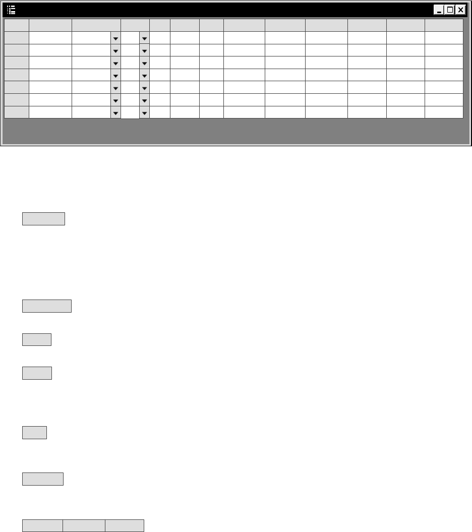
MPK DEVICES TABLE
MPK Devices
1
Dev Name
Dev Type Exp PW Board Port Address
Inp Set Out Set Lev Set
Over Set Seq Set
2
PC1MC2
PC1 1 23232323
MC−3000
3
PC1MC3
PC1 1 45454545
MC−3000
4
PC1MC4
PC1 1 67676767
MC−3000
5
PC1MC5
PC1 1 89898989
MC−3000
6
PC1MC6
PC1 1 90909090
MC−3000
N
N
N
N
N
3800 VM1 6 00C19E22
CP−3800
PC1MC1 PC1 1 01010101
MC−3000
N
N
3800INP 3800OUT 3800LEV
7
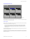
Figure 7−3.
Dev Name
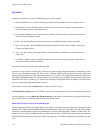
There must be an entry for at least one CP 3xxx control panel that is capable of machine con-
trol and that has Input, Output, and Level Sets assigned. (This is true even if no physical panel actually
exists.) A CP 3800 panel is shown in this example.
You must also create a name for each of the six Slaved Machine Control panels.
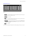
Dev Type
For the slaved machine control panels, select “MC−3000.”
Exp
For the software machine control panels the entry is always “N.”
Board
For the slaved machine control panels, enter the name of the PC that will display the software
panels; this must agree with the PC’s Board Name entered on the Network Description table (page
7−2).
Port
For the slaved machine control panels, there must be an entry in each of these fields to satisfy
the compiler.
Address
For the slaved machine control panels, there must be a unique entry in each of these fields to
satisfy the compiler.
Inp Set Out Set Lev Set
These fields are the source for the set names that appear on the Panel Config-
uration screen (page 7−7). For the six Slaved Machine Control panel entries, these fields must be blank.