


Venus DM 400/400A
L−10 CM 4000 Installation and Operating Manual
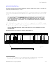
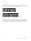
CP Input and Output Sets
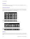
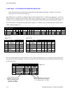
The input and output names in the previous tables must be assigned to Category/Entry selections. In the following examples,
intended for use with a CP−3000−type panel, the “C” (for “controller”) category button will be used to select the master VCR
and the “D” (for “destination”) category button will be used to select the slave VCR.
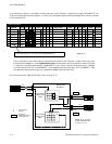
Figure L−15.
1
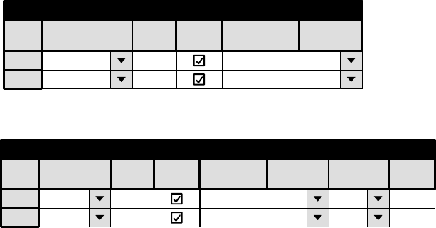
Input Set — KXYZ−INP
C 1 VR1M VR1−M
2 C 2 VR2M VR2−M
Category Entry Mnemonic
Logical
Auto
Mnem
Input
1
Output Set — KXYZ −OUT
D 1 VR1S VR1−S
2 D 2 VR2S VR2−S
Category Entry Mnemnonic Level Set Button
Auto
Mnem
Output
Logical
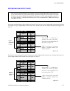
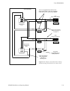
Operation
In this example, the operator might select a slave VCR destination such as “D−2” (VR 2); then select a master VCR source
(i.e., a controller) such as “C−1” (VR 1). When TAKE is pressed, the VR 1 transmit (Tx) signal is switched through the cross-
over cable to VR2; and, the VR 2 Tx signal is automatically switched back to VR 1. VR 1 is therefore the master and VR 2
the slave. If the operator selected input “C−2” and output “D−1,” then VR 2 would be the master and VR 1 the slave.