


Configurator
CP Input Set
5−72 CM 4000 Installation and Operating Manual
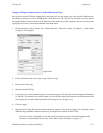
12. DD (“Diamond”) − serial
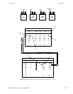
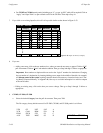
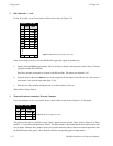
For the Serial table, you will need entries similar to those shown in Figure 5−54.
Figure 5−54. Diamond Serial Input Set menu.
1
Input Set — ASC−INP
2
1
2
Entry
BARS
TONE
Input
3
3
TC
4
5
4
5
6
6
VT03
7
7
8 VT05
VT01
VT02
VT04
48 47 ESS
0
Logical
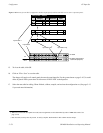
There are no category choices, since the DD identifies inputs and outputs by number only.
a. Specify the desired Entry (unit) number. This can be done by double−clicking on the desired “Entry” field and
typing the number. Press ENTER.
Each Entry number corresponds to a button on the DD Aux Bus. The buttons are numbered 0−47.
b. Select the name of the router Input that you want assigned to the first button on the DD Aux bus. The source of
these names is the Switcher Input table (page 5−48).
c. Enter the next Entry number and Input name, up to the maximum of 48 rows.
When finished, skip to Step 15.
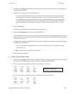
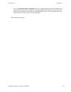
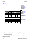
13. Thomson Broadcast Automation / External Computer
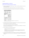
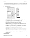
If you are entering a set for serial control device, a menu similar to that shown in Figure 5−55 will appear.
Figure 5−55. Serial Input Set menu.
1
Input Set — PC−INP
2
1
2
Entry
CAM1
CAM2
Input
3 3 VTR1
Logical
The purpose of the table is to establish a unique “Entry” number for each switcher “Input” name. In Figure 5−55, Entry
number “1” is associated with Input name “CAM1.” The Entry number is the number that the serial control device must
send to Jupiter. When the Entry number arrives, the software checks this table to find the associated Input name; then
the Switcher Inputs table (page 5−48) is checked to find the corresponding physical input number.