


Hardware Installation
2−15CM 4000 Installation and Operating Manual
SMS 7000 CONNECTIONS
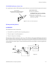
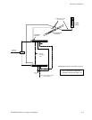
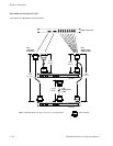
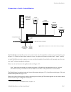
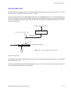
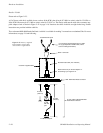
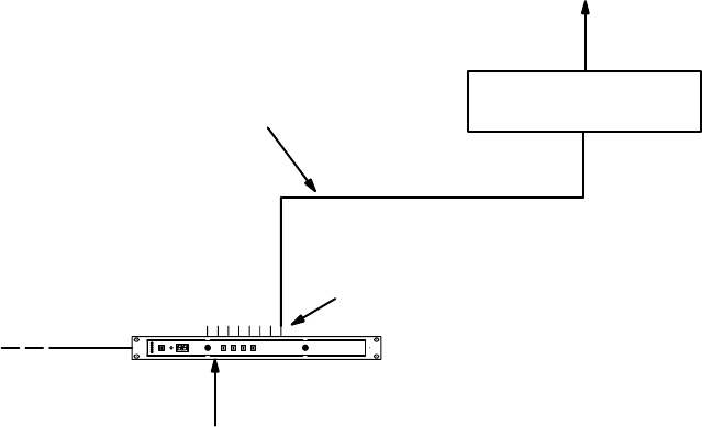
The CM 4000 can be connected to a Grass Valley SMS 7000 Signal Management System and router (see Figure 2−15). The
protocol setting is: 38400 baud, 8 data bits, no parity, 1 stop bit.
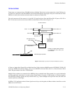
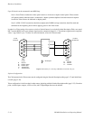
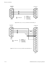
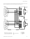
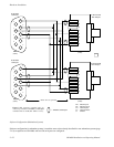
The serial cable on the back of the SMS 7000 controller frame may be labeled RS−232, but it can and should function as
RS−422 if configured in software. The CM 4000 is connected to one of the DB25 or DB9 ports on the back of the SMS 7000
controller frame. Refer to the manual supplied with the SMS 7000 for instructions on setting the port up for RS−422 and set-
ting the serial parameters.
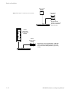
Figure 2−15. Connection to SMS 7000 Control System.
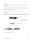
See page 2−16 for a description of this cable
GNP protocol
to Series 7000 routing switcher
SMS 7000 control system
House time
code
(optional).
See pg.
2−64
CM 4000 System Controller
Serial Port
LAN
Software Configuration
The CM 4000 connected to the SMS 7000 must be configured using the Network Description table (page 5−27) and Serial
Protocol table (page 5−30).
The router must be defined on the Switcher Description table (page 5−35). From that point, switcher inputs, outputs, a CP
Level Set, and CP input/Output Sets must be defined.