


Hardware Installation
2−38 CM 4000 Installation and Operating Manual
SWITCHER CONTROL PANELS
CP 300 Series
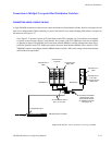
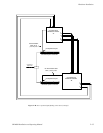
Power supply requirements − A wall plug−in power supply is supplied with each 300 Series panel that will be used with
110 VAC 60 Hz power. Panels that are to be used in areas where 220VAC 50Hz power is the norm are not shipped with any
power supply; the user in these areas must provide a source of regulated 5 VDC power to each panel. The power requirement
is +5 VDC +/− 0.25 V at 600 mA. The power connector used on the 300 Series PC board is an RL11A (female) made by LZR
Electronics; Grass Valley part no. 30−005724−007.
Note: An optional PS 300 power adaptor kit provides all hardware needed to modify one CP 300 Series control
panel for direct connection to a power line. See Appendix Q.
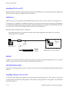
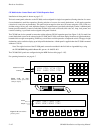
DIP switch settings − A DIP switch, accessible through an opening in the rear panel, must be set with switch 8 OFF when
a 300 Series panel is used in a Jupiter system; the remaining seven switches are ignored. This sets the panel address to the
one stored in PROM (which is stamped on the rear panel).
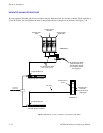
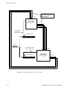
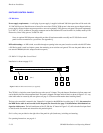
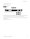
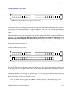
CP 300 24 X 1 Single Bus Control Panel
Installation is shown on page 2−37.
CHG
VID
CHG
A1
CHG
A2
CHG
A3
CHG
A4
CHG
A5
012
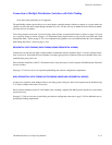
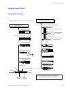
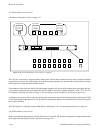
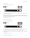
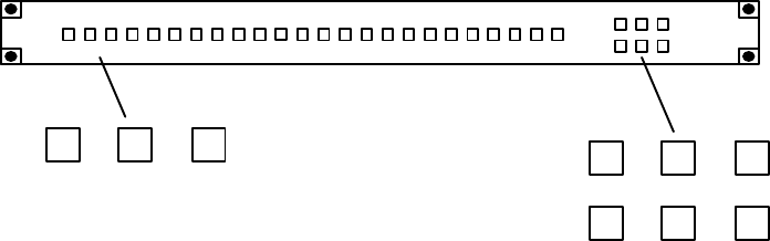
Figure 2−43. CP 300 Control Panel (as supplied).
(etc.)
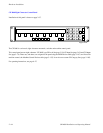
The CP 300 is a single bus control panel that can select one of 24 inputs. The push buttons illuminate to indicate status and
can be fitted by the user with transparent labels. The panel is shipped with input and level labels as shown in Figure 2−43—any
other labels must be created by the user (please see page 2−58 for more information about installing labels).
The bus to be controlled is entered in the “Output Set” assigned on the MPK Devices table (page 5−107). Also entered on
the MPK Device table is an Override Set for the panel; the Override Set (page 5−96) determines which button is as-
signed to which source. The left−hand button of the CP 300 (the “0” button in Figure 2−43) will select the first input listed
on the Override Set created and selected for this particular panel.
Six Level keys are provided on the right side of the panel for split (breakaway) switching and statusing.
For operating instructions, see page 6−1.