


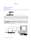
VGA
A−5CM 4000 Installation and Operating Manual
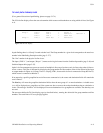
Definition Syntax Key: VGA Color Color Code
−−−−−−−−−−−−−−−−−−−−−− −−−−−−−− −−−−−−−−−−
n = Color Code White 0
oooooooo = 8 char System Output Name Yellow 1
iiiiiiii = 8 char System Input Name Magenta 2
llllllll = 8 char System Level Name Red 3
ssssssss = 8 char System Switcher Name Cyan 4
pppp = 4 digit Physical Output Number Green 5
mmmmmmmm = 8 char System Machine Control Device Name Blue 6
dddddddd = 8 char Delegation Group Name Dark White 7
bbbbbbbb = 8 char System Board Name Brown 8
−−−−−−−− = User defined screen text (any length) Dark Blue 9
xx = 2 digit Button Number
ggg = 3 digit group number (0−999)
ee = 2 digit line number (0−99)
Box Drawing Characters (IBM Line Characters)
−−−−−−−−−−−−−−−−−−−−−−−−−−−−−−−−−−−−−−−−−
Character Converted to:
−−−−−−−− −−−−−−−−−−−−−
+ Corners of a box, or intersections of vertical and horizontal lines
− Horizontal Lines
| Vertical Lines
For example, a simple box, divided into four squares inside, would be defined like this:
+−−−−+−−−−+
| | |
| | |
| | |
+−−−−+−−−−+
| | |
| | |
| | |
+−−−−+−−−−+
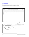
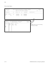
As a quick demonstration of the VGA Page Description File syntax, to display the status of the switcher output “VTR1” of
the switcher name “DEFAULT,” on levels “VIDEO,” “LEFT,” and “RIGHT,” the formatting instructions would look like this
(assuming “<TAB>” is substituted with a real <TAB> character):
SDEFAULT
O0VTR1<TAB>T0 <TAB>l0VIDEO<TAB>T0 <TAB>l0LEFT<TAB>T0 <TAB>l0RIGHT<TAB>
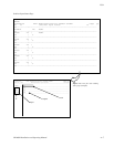
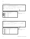
The letters “S,” “O,” “T,” and “l” (small L) define the type of field of the following text. The number “0” after the letters “O,”
“T,” and “l” corresponds with the color the data will appear on the screen.