


Configurator
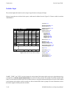
Switcher Output Table
5−56 CM 4000 Installation and Operating Manual
S−T
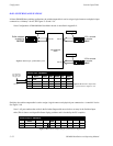
A Security Board Type can be entered. Only controls connected to a control board of that type could then
be used to switch the output. A dash (“−”) entry means “none.” The board types that can be selected are “VM”
and “SI.”
Note: In systems with CM 4000/Jupiter XPress, this field should be left blank (since Jupiter XPress
cannot be used in a system that includes VM/SI controllers).
Pass
word
A password level can be entered for the output. This is described in detail below.
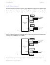
In Venus DM 400B data switching applications, the switcher output table is used to assign a logical name to each physical
port connected to a “controller” device. For more information, see page 5−52.
ENTERING OR EDITING OUTPUT NAMES AND NUMBERS
1. On the top of the Jupiter Configurator window (page 5−2), check to see whether the configuration set you want to
change is selected for editing.
In most cases, you will want to modify the set that is currently active; if so, you may want to copy the active set and
select the copy for editing. For more information, please see Copying a Configuration Set for Editing on page 5−10.
2. Click on “Jupiter” and “Switcher Input.” This will open a list of all existing Switcher Output tables (or open the table
if there is only one).
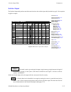
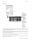
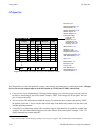
3. Click on the desired switcher input table name and “Edit.” Selecting the switcher name will bring up a table similar to
that shown on page 5−55.
4. Enter/edit the desired logical name and physical output numbers for this output. Guidelines for using the editor are found
on page 5−3. For information about password levels, please see page 5−57.
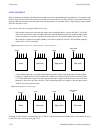
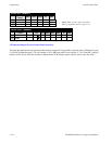
Important: Mars physical output numbers, when controlled by a Jupiter system, are not continuous. For
example, physical output numbers 8 through 15 are skipped. For more information, refer to the Cross-
point/Jupiter control section in the Mars manual.
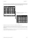
Important: When adding new items to tables, add them at the end if possible. Changing row numbers on
the Switcher Output table will cause panels to control different outputs than those to which they had been
assigned.
Important: Row numbers on Jupiter tables are used as the “logical” numbers for destinations. Changing
the row number of a destination (by inserting/deleting a new output in the middle of the table, for example)
will disrupt control of the system, requiring controller boards to be memory−cleared and reset (see “Clear-
ing Battery−Protected Memory” in Appendix B). One way to avoid this interruption is to add new outputs
at the end of tables.
Note 1: Some switchers (such as Apex, late−model Trinix, Concerto, and Triton) use “1” as the first connec-
tor number. In this case, the physical output number for this connector, as entered on the table, is “0.” Connec-
tor “2” is physical output number “1,” etc.