


Configurator
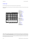
Switcher Input Table
5−49CM 4000 Installation and Operating Manual
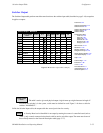
Note: an input name is not entered directly at switcher control panels; rather, it is linked to a category and entry
number through the CP Input Sets table. The category and entry number are then entered at the control panel to
make the switch. The status mnemonic that appears on control panels is also determined by the CP Input Sets table.
For more information, see page 5−62.
Important: Mars physical input numbers, when controlled by a Jupiter system, are not continuous. For example,
physical input numbers 8 through 15 are skipped. For more information, refer to the Mars manual in the Cross-
point/Jupiter control section.
Note: Some switchers (such as Apex, late−model Trinix, Concerto and Triton) use “1” as the first connector num-
ber. In this case, the physical input number for this connector, as entered on the table, is “0.” Connector “2” is physi-
cal input number “1,” etc.
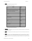
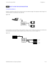
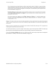
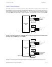
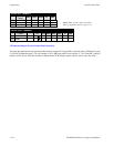
In Figure 5−35, there are four levels: video, left audio, right audio, and time code. The table shows that the input named
“VT01” is wired to connector 001 on all four levels. Similarly, the input name BARS is associated with connector 000 on
all four levels.
If there is no entry for a particular level, no switch will occur on that level. On this table, when input “TC” is requested from
a control panel, only the time code level will switch.
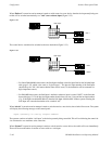
An automatic split (breakaway) can also be arranged. In this example, a request for the input named “TONE” will obtain input
064 on the video level but input 000 on the other levels. Split switching is described in more detail below.
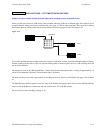
In Venus DM 400B data switching applications, the switcher input table is used to assign a logical name to each physical
port connected to a “tributary” device. For more information, see page 5−52.