


Configurator
Machine Control Table
5−143CM 4000 Installation and Operating Manual
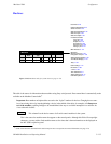
EXAMPLE OF MACHINE CONTROL TABLES SETUP
1
Machine Control
Device Name Device Type
Delegation
In/Out
Associated
2
TAPEMC MC−3000E Out PRDA
3
Mnemonic
TAPEMC
VT01
Sony Mch In VT01
VC01
Sony Mch In VC01
VC02 Sony Mch In VC02
4
Group Name
VT01
VC01
VC02
1
Machines
2
VT01 Sony Mch CM1 1 2
VC01 Sony Mch CM1 2 2
MPK Devices
MPK
Expansion
Pass
Board Port Address Input Sets Output Sets Level Set Overide Set Sequence Set
2 TMC3010 MC−3010 CM1 6 00000029
Devices word
In Panel Out Panel
1 TAPEMC MC−3000E CM1 6 00000016
3 VC02 Sony Mch CM1 3 2
TAPEMC MC−3000E Out PRDBTAPEMC5
TAPEMC MC−3000E Out PRDCTAPEMC6
TMC3010 MC−3010 Out PRDXTMC30107
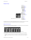
Figure 5−122.
Device
Type
Name Type
Board Port Address Preroll
Machine
Device
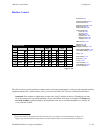
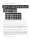
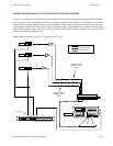
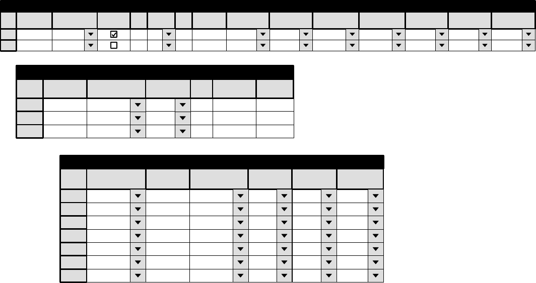
The Machine Control table shown in Figure 5−122 corresponds to the system shown in Figure 5−121. The applicable entries
in the MPK Devices and Machines tables are shown for reference.
The “Associated Name” is the name of the routing switcher input or output to be associated with this particular device.
The first three rows show the names of the machines in the system and the associated routing switcher input names.
The next three rows (4, 5, and 6) relate to the SELECT buttons on the MC 3000 expansion panel; the order of entry on this
table will be the same as the order of buttons on the panel. In this example, we want the first SELECT button to be assigned
to whatever VTR is feeding routing switcher output “PRDA;” this is the output that feeds input A of the production switcher.
Associated names are also entered for the following two SELECT buttons: “PRDB” and “PRDC.”
The next row (7) is similar to the entries just described, but pertains to the MC 3010 Dual 4 Machine Control panel. Again,
the order of entry on this table will be the same as the order of button groups on the panel.
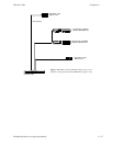
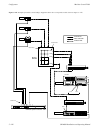
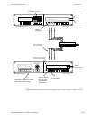
Given this table, Figure 5−121 shows what will happen when the indicated routing switcher crosspoints are closed. For exam-
ple, the VTR “VT01” is shown switched to input A of the production switcher; that is, routing switcher input VT01 has been
switched to output PRDA. The system will locate these two input/output names in the Machine Control table and find that
control of VT01 must be assigned to the first SELECT button on the MC 3000 expansion panel. The device name and status
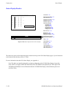
for VT01 will be sent to the status displays indicating that control of the machine is now linked to this panel. (A detailed view
of the MC 3000 expansion panel displays is shown in Figure 5−123.)