


Configurator
Tally
5−152 CM 4000 Installation and Operating Manual
Tally
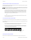
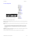
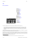
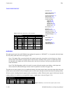
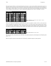
RELAY DESCRIPTION
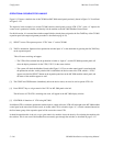
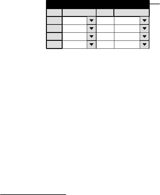
Figure 5−132. Tally Relay description table.
1
Tally Relay
Tally Device
TALLY1
Relay
0
Logical Input
VT01
2
3
TALLY1 1 VC02
TALLY1 2 VC01
4
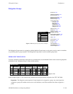
Password 5−22
Network Description 5−27
Serial Protocol 5−30
Switcher Description 5−35
Switcher Input 5−48
Switcher Output 5−55
Control Panel Sets
Level set 5−58
Input set 5−62
Output set 5−78
Override set 5−96
Sequence set 5−99
Category set 5−101
MPK Devices 5−107
Machines 5−135
Machine Control 5−139
Delegation Groups 5−149
Status Display Header 5−150
VGA Status Display 5−151
Tally
Path Finding 5−174
Exclusion 5−188
Y Line 5−189
Time Standard G−11
Video Reference G−14
CM VGA Options H−1
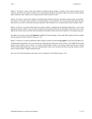
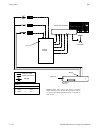
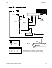
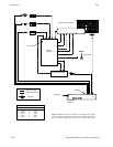
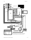
An overview of Jupiter tally and a discussion of hardware installation can be found on page 2−67.
Note: The Jupiter Tally software package described here cannot tally sources that are wired directly to a Saturn
internal matrix. If the Saturn is equipped with an internal matrix, the Saturn Tally system is available (but cannot
be connected to the Jupiter Tally system). Please refer to the Saturn installation/operating manual for additional
information.
The Relay Description table must be used when an MI 3040 has been configured to operate as a “MI 3040/T,” i.e., for operation
with tally lamps. The Tally Dependency table must also be used (page 5−158 ).
The table has a one−row entry for each of the tally lights in the system. The entry shows the name and relay number of the
MI 3040 connected to each light; the source of this name is the MPK Devices table (page 5−115). Each relay is associated with
the name of a routing switcher input, so that whenever that input is switched to air the relay will close. The source of the
switcher input names is the Switcher Input table (page 5−48).
§
Some of the functions described in this section may be extra−cost options. For more information, see page 1−27.