


Hardware Installation
2−43CM 4000 Installation and Operating Manual
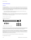
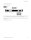
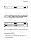
CP 3020 Push Button Control Panel
Figure 2−50. CP 3020 Push Button Control Panel with example labels.
C1 C2 C3 C4 T1 T2 R1 R2 NTV1 V2 V3 V4 V5 SA SB E1 E2 E3
LOCK CHOP
V6
Installation of this panel is shown on page 2−37.
The CP 3020 is a single−bus control panel that can select one of 20 inputs. The push buttons illuminate to indicate status and
can be fitted by the user with transparent labels. The panel is shipped with “Lock” and “Chop” labels and a general purpose
“0−99” label set—any other labels must be created by the user (please see page 2−58 for more information about installing
labels).
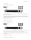
The logical name of the switcher bus (output) that is to be controlled is entered in the “OutSet” column on the MPK Devices
Table (page 5−107). Also entered on the MPK Device table is an Override Set for the panel; the Override Set (page 5−96)
determines which button is assigned to which source. The left−hand button of the CP 3020 (the “V1” button in Figure 2−50)
will select the first input listed on the Override Set created and selected for this particular panel.
For operating instructions, see page 6−26.
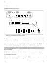
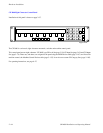
CP 3021 Push Button Expansion Panel
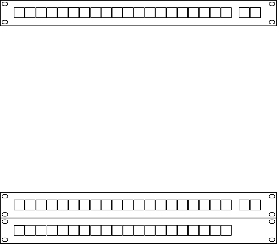
Figure 2−51. CP 3020 Push Button Control Panel with CP 3021 Push Button Expansion Panel with example labels.
LO1 LO2 LO3 LO4 81 82 41 42 DMM1 M2 M3 M4 M5 LR LS P1 P2 P3RR
C1 C2 C3 C4 T1 T2 R1 R2 NTV1 V2 V3 V4 V5 SA SB E1 E2 E3
LOCK CHOP
V6
Up to four CP 3021 Push Button Expansion panels can be added to the CP 3020, allowing button−per−input selection of up
to 100 inputs. Each CP 3021 is supplied with a 12−inch (305 mm) ribbon cable with installed 37−pin connectors; the cables
loop through each expansion unit.
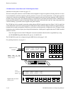
The left−hand button of the CP 3020 (the “V1” button in Figure 2−51) will select the first input listed on the Override Set
created and selected for this particular CP 3020. The left−hand button of the first CP 3021 on the ribbon wire bus (the “M1”
button in this example) will select the 21st input listed, etc.
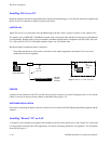
Note: The “remote” connector of the CP 3020 must be connected to the “input” connector of the first CP 3021;
the “output” connector of that CP 3021 must be connected to the “input” connector of the next CP 3021, etc.