


6−1CM 4000 Installation and Operating Manual
Section 6 − Control Panel Operation
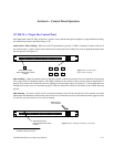
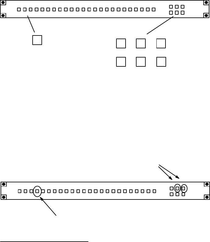
CP 300 24 x 1 Single Bus Control Panel
Each input button of the CP 300 is assigned to a specific source (and the entire panel assigned to a single destination) during
the installation procedure described on page 2−38.
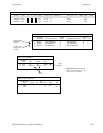
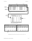
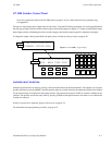
Audio−follow−video switching - When one of the 24 input buttons is pressed, a TAKE* command is issued to all levels of
the switcher matrix. A status* signal is then returned to the control panel; this confirms the action by lighting the input button
that was pressed. See Figure 6−1.
CHG
VID
CHG
A1
CHG
A2
CHG
A3
CHG
A4
CHG
A5
1
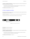
Select desired input;
button will light when switch
is made.
Figure 6−1. CP 300 audio−
follow video switching.
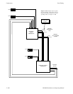
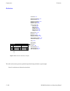
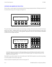
Split switching − When the operator desires to take only specific switcher levels, those levels are defined by first pressing
one or more of the six breakaway buttons. The TAKE command to the switcher will be executed when an input button is
pressed. The switcher will confirm the action by lighting the selected input button. (See Figure 6−2.) If the panel has been
configured for sticky levels (as described on page 5−108), the selected level buttons will remain lit after TAKE has been
pressed.
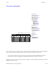
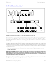
Split statusing − To status a specific level of a previous breakaway level switch, select the level to be statused; one of the
input buttons will illuminate to indicate the source for that level. If more than one level status button has been toggled on (like
A1 and A2), only the lowest level (A1) will be statused.
Figure 6−2. CP 300 Split (breakaway) switching.
1. Select level(s)
to be switched.
2. Select desired input;
button will light when switch
is made.
* Defined in Glossary Section