


Venus DM 400/400A
L−8 CM 4000 Installation and Operating Manual
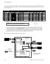
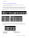
Y LINE TABLE − VTR CONTROLLER/TRIBUTARY SELECTION
Note: These instructions assume that the installer has read “Data Matrix Installation” in Section 3 of the Venus
Routing Switcher System Technical Manual.
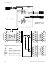
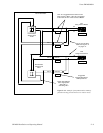
Some VTRs can act as controllers or tributaries. These can be connected with a “Y” cable to two Venus ports— one for use
when the VTR is a controller, the other when the VTR is used as a tributary (see Figure L−14). If the VTR is operated only as a
controller, or only as a tributary, then a “Y” cable will not be needed; the cable can instead be one of those shown on page L−4.
The following tables correspond to the system shown in Figure L−14. The basic rules for these tables have already been de-
scribed (starting on page L−3).
1 SAFE
FOR
2
VR1−M
3
VR2−M
REV
192
003
001
003
Switcher Input − DATA
1
Switcher Output − DATA
SAFE
Security S−T
−
FOR
016
REV
2
VR1−M
− 0013
VR2−M
− 003
4
5
VR1−S
− 000
VR2−S − 002
001
4
VR1−S
3
VR2−S
002
000
002
000
5
192
Figure L−10.
Figure L−11. Figure L−12.
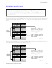
Name
Logical Input
Name
Logical Input
Pass
word
1
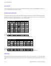
Switcher Description
2
Switcher VI RV Board #In #Out PLvL Follow Level Driver 3 LI 3 LO Option AudioLevel
DM 400
MC
Off Time
DATA VM1 193 32 16 Binary EFOR
DATA VM1 193 32 16 FOR (DATA) Binary EREV
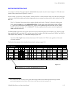
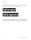
The Y Line table informs the system controller of a level, input, and output that have a Y line installed. Notice that each Y
line requires two entries, and that the “crossover” ports (the “M” ports) are listed as inputs on the forward level and outputs
on the reverse level:
Figure L−13.
Drop−down menu shows
“Switchers” and “Names” from
Switcher Description table
(Figure L−10). Select
appropriate data switcher.
Select the appropriate name from those
already entered on the Input (Figure
L−11) or Output (Figure L−12) table.
1
Y Line Table
Level
REV (DATA)
2
FOR (DATA)
Input
VR2−S
Output
VR2−M
VR2−M VR2−S3
REV (DATA)
4
FOR (DATA)
VR1−S VR1−M
VR1−M VR1−S
Logical
Logical