


Control Panel Operation
CP 300 Series
6−4 CM 4000 Installation and Operating Manual
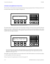
Before the TAKE push button is pressed, the desired Breakaway Level push buttons are pressed to designate the levels to be
switched.
Another input selection is then made using the category/number push buttons. The desired Breakaway Level push buttons
are again selected corresponding to the levels to be added to the switcher TAKE command.
The TAKE button is then pressed, causing the switcher to perform the split, using the two designated inputs from the desired
levels.
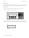
Protecting the current switcher output - To protect the current output of the switcher, the PROTECT push button is pressed.
The PROTECT lamp will remain on to indicate the protect mode.
The protected status will also be displayed by other control panels presently controlling the protected output; if the other panel
is a CP 320 the PROTECT button will blink.
Only the control panel that originated the protected status can remove it (the originating panel can be recognized by the steady
illumination of the PROTECT lamp). To remove the protected status, press the lighted PROTECT push button. The button
light will go out to show the protected status has been removed.
For additional protect/lock information − see page 6−12.
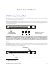
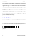
CP 328 Push Button Control Panel
Operation of this panel is the same as the CP 320. The only difference between the panels is that the CP 328 has eight−character
display windows while the CP 320 has four−character display windows.
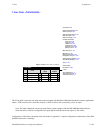
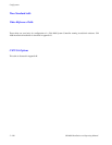
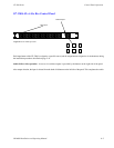
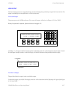
CP 330 Control Panel
The CP 330 can be configured to operate as a 48 x 1 panel, or, as a 24 x 2 panel with the top row of buttons assigned to one
output and the bottom row to another. Operation is much the same as a CP 300, as described on page 6−1.
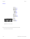
Figure 6−5. CP 330.
(For installation and configuration instructions, please see page 2−38.)