


Configurator
CP Input Set
5−74 CM 4000 Installation and Operating Manual
14. CP 3832 / CP 3864
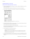
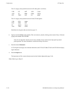
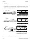
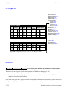
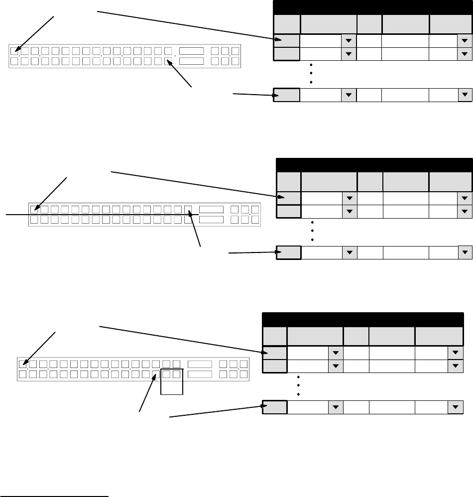
If you are entering a set for CP 3832 or CP 3864 (including type “L”), a menu similar to that shown in Figure 5−56
will appear. The purpose of the table is to assign a button position (row number) to each switcher “Input” name. In Figure
5−56, button position “1” will be used to select input “CAM1.” Note that destination buttons are defined on a CP Output
Set (page 5−78). Exact table entries will depend on the panel and the application, as shown in the following examples.
For Category, the word “default” is used for all entries.
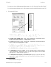
Input button 1
CP 3832
Input button 32
Figure 5−56. Entries for CP 3832 configured as single−
bus panel.
1
CP Input Set − 3832−IN
default
2 default
1
2
Category Entry
CAM1
CAM2
Input
32 default 32
VTR12
CAM1
CAM2
Mnemonic
VTR12
†
†
†
Logical
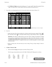
Input button 1
CP 3832
Input button 16
IN
OUT
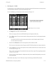
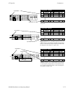
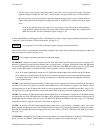
Figure 5−57. Entries for CP 3832 configured as “bal-
anced split” panel. Balanced number of input/output
buttons is determined by output assignments made on
the CP Output Set. For details, see page 5−90.
Category
1
CP Input Set − 3832−IN
default
2 default
1
2
Entry
CAM1
CAM2
Input
16 default 16 VTR12
CAM1
CAM2
Mnemonic
VTR12
†
†
†
Logical
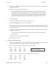
Input button 1
CP 3832
Input button 30
IN
OUT
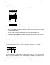
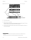
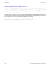
Figure 5−58. Entries for CP 3832 configured as 30 x 2
“unbalanced split” panel. Total number of input buttons
vs. total number of output buttons is determined by num-
ber of output assignments made on the CP Output Set.
For details, see page 5−90.
Category
1
CP Input Set − 3832−IN
default
2 default
1
2
Entry
CAM1
CAM2
Input
30 default 30 VTR12
CAM1
CAM2
Mnemonic
VTR12
†
†
†
Logical
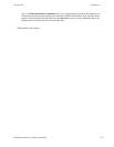
†
Data not used, but entry must be present to satisfy compiler. Each number in this column must be unique.