


Configurator
CP Override Set
5−98 CM 4000 Installation and Operating Manual
Guidelines for using the editor are found on page 5−3.
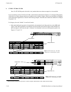
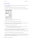
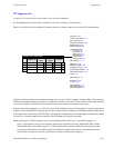
8. In the “Input” column, select the name of the switcher input for the first override button.
The source of these names is the Switcher Input table (page 5−48).
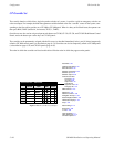
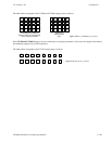
Although the CP 3824 has only 24 button−per−input keys, up to 360 inputs can be assigned on this table, i.e., 15 groups
(“pages”) of 24 inputs each. Each page of 24 sources would then be accessed with the Page key.
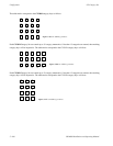
For CP 330 panels configured for dual bus control (24 x 2), the first 24 rows on this table will apply to the top row of
24 buttons and the next 24 rows to the bottom row of buttons.
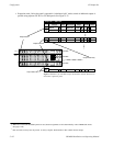
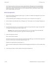
9. If you want to allow the override to be changed from the CP 3000, CP 3800, or CP 3824 front panel, check the box in
the “Edit” column.
Note: Front−panel editing does not change the name of the override as established by the Override Set table.
This could result in a situation where the operator selects CAM1 but gets VTR5. For overrides that will be
allowed to be edited from the front panel, it’s a good practice to enter generic names such as “Usr1” or
“Ovr1.”
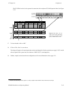
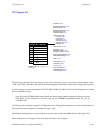
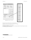
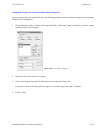
10. Select the Levels that you want to switch by double−clicking in the appropriate Levels field; this will open a secondary
dialog box showing the names of existing switcher levels (as shown in the Switcher Description table [page 5−35]).
Toggle the desired levels on or off and click OK.
11. To close the Override Set table, click OK.
12. Click on “File > Save” to save the table.
The change will apply to all control panels that use the same override set. For the system shown on page 5−89, it would
affect all CP 3000 panels in the system since all of them use “KXYZ−OVR” as the override set.
13. After saving your changes, compile and activate the configuration set. (See page 5−13 if you need more information.)