


Configurator
Switcher Description Table
5−40 CM 4000 Installation and Operating Manual
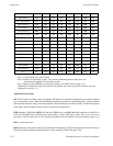
Note: If non−factory default numbers are used, the following rules should be kept in mind: 1) For analog
audio left levels, and for digital audio levels, the binary form of the physical level number cannot have the 4s
bit set to 1; e.g., decimal ”2” (binary 00000010) can be used for analog audio left but decimal ”4” (binary
00000100) cannot. This means that the following decimal numbers cannot be used: 4 through 7, 12 through
15, 20 through 23, 28 through 31, 36 through 39, 44 through 47, 52 through 55, 60 through 63, etc. 2) The
analog audio right level number must be the left number + 4.
d. Concerto switchers are configured much the same as Venus. For more information, refer to Grass Valley Field
Engineering Bulletin 075−0722−00, “Jupiter Crosspoint Bus Control of Concerto Flexframe Routing Matrix.”
e. Triton switchers, when controlled by Jupiter, use a level scheme different than that described in the Triton manual.
In Jupiter applications, split switching requires each level to be assigned a different number.
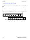
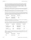
Entries in the PLvL column consist of three digits. The first digit serves only to differentiate the table entry from
all other physical levels connected to the CM; the second two digits are derived from the “Router Address” DIP
switch [setting on the rear panel. In a typical video/audio/time code application, the first digit could be “1,” while
the last two digits would be the Router Address for the chassis. For example:
Triton chassis DIP switch setting PLvL entry
Video 0010 (decimal 02) 102
Left and right audio 0000 (decimal 00) 100
Time code 1111 (decimal 15) 115
Note that split switching is possible, but only between chassis; e.g., it is possible to split Audio Left/Right from
Video, but not possible to split Audio Left away from Audio Right.
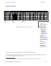
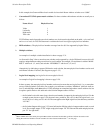
As a convention, it is suggested that all Triton chassis connected on the same MIDI bus use the same first digit.
Thus if there were a second “group” of Triton switchers connected on another MIDI bus (and per Jupiter require-
ments connected to a second CM), they might have “2” as the first digit in the PLvL entry. For example:
Triton chassis Connected to DIP switch setting PLvL entry
News Video CM2 0010 (decimal 02) 102
News Left and right audio CM2 0000 (decimal 00) 100
News Time code CM2 1111 (decimal 15) 115
Aux Video CM5 0010 (decimal 02) 202
Aux Left and right audio CM5 0011 (decimal 03) 203
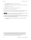
In RGB or YUV applications where all three signals must always switch together, the Router Address switches
should be set to the same value on each chassis. However, the Switcher Description table has only one row cover-
ing all three chassis. For example:
Triton chassis DIP switch setting PLvL entry
Red 0000 (decimal 00) 100