


GV 8964OMD OSD Module
CM 4000 Installation and Operating Manual T−3
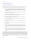
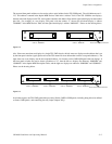
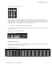
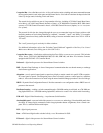
Figure T−4. Serial−type CP Input Set (example).
1
Output Set − MNF−Out
2
1
2
Entry
STU1
SVR1
Output
3
3
SVR2
4
5
6
VT01
0
Logical
The Entry number is used to identify an OSD board and channel number, which is then associated with a Logical
Output number of the router. For example: Entry “0” = module 0, channel 0; this channel will monitor the status of
router output “STU1.” “3” would be module 0, channel 3; it will monitor router output “VT01.” If there is another
module, then the next row would show Entry “4” for module 1, channel 0, etc.
Note: Module 0 is the module furthest from the power supply.
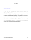
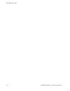
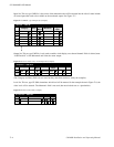
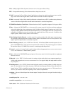
Level Set. This placeholder set, type CP 3000, must be created with at least one Level entry. See Figure T−5. The
entries are not used.
Figure T−5. Placeholder CP Level Set table (example).
1
CP Level Set — MNF−LEV
Mnemonic Level Break Switch
2
aaaa VIDEO
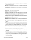
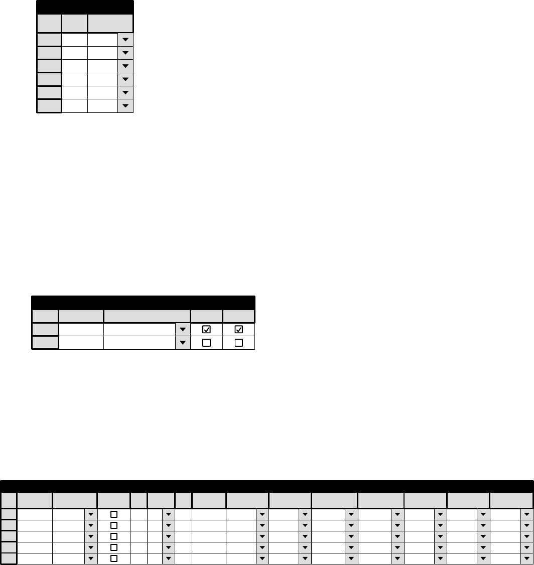
OSD Module channel entries
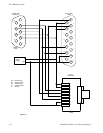
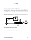
Each OSD channel also requires an entry on the MPK Devices table consisting of an MPK Device name, a Device
Type, and the names of three sets. See Figure T−6.
Figure T−6. MPK table (example).
MNF1 MNF MNF−IN MNF−OUT
OSD0 OSD
OSD−IN OSD−OUT
1
MPK Devices
MPK
Expansion
Pass
Board Port Address Input Sets Output Sets Level Set Overide Set Sequence Set
2
OSD−LEV
Devices word
In Panel Out Panel
MNF−LEV
Device
Type
3
OSD−LEV
4
OSD−LEV
5
OSD−LEV
OSD1
OSD OSD−IN
OSD−OUT
OSD2
OSD
OSD−IN
OSD−OUT
OSD3
OSD OSD−IN OSD−OUT
A device name is created here for each OSD channel. The Device Type is “OSD.” Three CP sets must also be specified.