


Hardware Installation
2−81CM 4000 Installation and Operating Manual
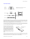
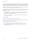
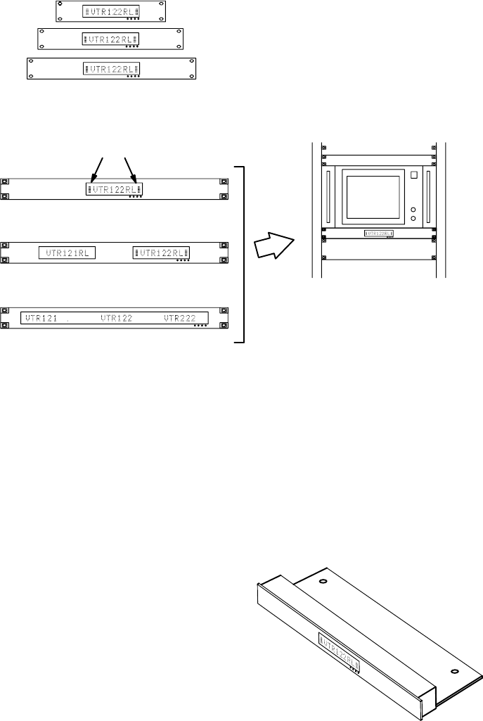
Under Monitor Displays
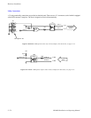
Figure 2−94. SlimLine Under Monitor Status Displays
(Standard screw mount models shown).
UMD 19 DD
Tally indicators
UMD 19 SD
UMD 19 UD
UMD 9 SD
UMD 12 SD
UMD 14 SD
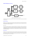
Using Under Monitor Displays, the Jupiter system can display the name of a source (camera, VTR, etc.) when it is switched
through a Jupiter−controlled router to a particular monitor. In multi−switcher applications, the system can follow a source
through as many as five switchers, including production switchers and Saturn master control switchers. Also available is a
fixed mode of operation, during which the desired source name is displayed permanently.
The Grass Valley SlimLine UMD SD/DD/UD displays shown above can be configured with some character positions used
as “tally lights”; these lights can be configured to illuminate when the source shown is switched to a particular destination
(e.g., on−air). The SlimLine displays are available in 9−, 12−, 14−, and 19−inch−wide versions.
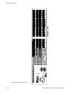
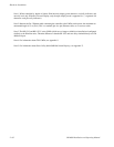
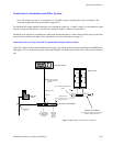
Each type is also available in a space−saving plate−
mount (“OB”) version for installation in front of a
monitor, i.e., in front of the monitor’s controls, not
the screen (see Figure 2−95). The mounting plate
slides under the monitor and a hinge allows the dis-
play to swing down when the monitor controls re-
quire adjustment. For more information, refer to the
equipment dimensions on page 1−15 and to the
SlimLine Under Monitor Displays Technical
Manual.
Figure 2−95. OB version
of UMD 19 SD.
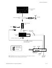
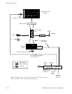
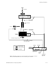
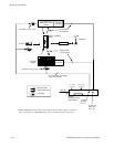
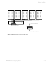
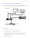
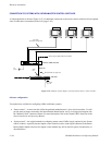
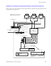
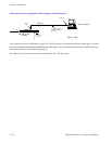
Installation of the SlimLine Controller and UMDs is shown below. Up to 16 various UMD models can be mixed or matched
per SlimLine Controller. Multiple SlimLine Controllers can be daisy chained on the MPK bus if desired; in which case the
associated rear−panel switch is set to “0” (non−terminate) instead of “1” (terminate MPK bus).